Automated Biochar Injection System
| Mean Clean Water Machine Team | |
| Sponsors | Gregory Möller, Ph.D. [UI Clean Water Machine] |
| Team Name | Mean Clean Water Machine |
| Duration | Fall 2018 - Spring 2019 |
| Faculty Advisor |
|
| Mentor |
|
| Client |
|
| Team Members |
|
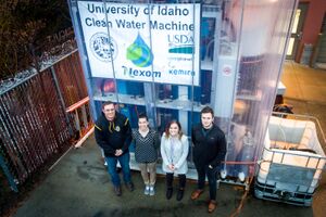
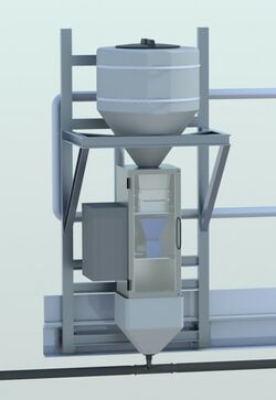
The goal of the project is to design a mobile BioChar (BC) injection system that will accept and inject BC into pressurized water lines in an accurate, controlled, and recorded manner in tandem with existing systems on the UIdaho Clean Water Machine with minimal adaptation of current systems.
To see a brief video of the completed project, click here: Automated Biochar Injection System Project
Problem Definition[edit | edit source]
Background[edit | edit source]
Extensive algal bloom induced eutrophication and phosphorous resource limitations are current problems faced by communities globally, primarily regarding agricultural fertilization and waste products. The University of Idaho capstone teams in the past have partnered with Nexom and other entities to create the Clean Water Machine, an upward-circulating sand filtration system, to address nutrient pollution and purify the wastewater. Current research is being conducted into the addition of biochar, biomass charcoal created by burning wood products and other organic material, into the system to absorb pollutants, especially phosphorous, from the wastewater. The BC can then be recovered and recycled as a fertilizer to amend soil quality. Currently, the Clean Water Machine operator must manually dose the BC, which results in an inconvenient and inconsistent process. Our goal as a team is to create a system that integrates cohesively with the current Clean Water Machine and automates the biochar dosing process into the influent wastewater flow to eliminate that step for the operator. Upon completion of this objective, the Clean Water Machine will have a convenient and controlled BC dosing mechanism, so that further research into water security solutions may be conducted efficiently and effectively.
Deliverables[edit | edit source]
Specifications[edit | edit source]
| Category | Requirement |
|---|---|
| 1. Functional | Operate quieter than 60 dB when at maximum capacity |
| Maintain 15% dosing accuracy, with no overdosing, at moisture contents from 0-10% | |
| Include touch-screen controls which must last 24 hours without recharging | |
| Must keep BC at constant conditions (temperature and moisture content) | |
| 2. User Interface | Operator will be able to specify amount of BC required |
| Operator will have digital readouts for all sensors | |
| Operator will have both manual and automatic control of mechanism | |
| 3. Mechanical | Pipe will withstand flow rate and pressure of 15 gal/min and 25 psi respectively |
| Hopper must handle load that lasts 3 days without refill | |
| Injection system should be reasonably accessible for maintenance | |
| No more than one 5-minute operation/ maintenance check per day | |
| 12 hours to completely disassemble and reassemble | |
| System should be modular to allow disassembly for travel | |
| All components (including bearings) shall have 90% reliability | |
| System shall operate for 8760 hours (approximately 365 days) without major maintenance | |
| Clear material where possible; green, blue, black, metallic finish where color | |
| The structure should fit within a 3’ x 3’ x 2’ space, design within the 10x10’ space of Clean Water Machine | |
| 4. Electrical | Input will be 120V or 240V, controls operating at 24V and 4-20mA |
| Function with the two 15A breakers available for use | |
| No energy storage in hopper; exclusively powered via external voltage source | |
| 5. Software | Standard WIFI 802.11, at least two USB 3.0 busses, 10-finger touch capability |
| System must have in-field programmability | |
| Display hopper capacity (g), flow rate at inlet and outlet (gal/min), temperature (ºF), moisture content (%), BC dose rate (g/mL) | |
| Performance indicators for malfunction and warning for hopper capacity | |
| 6. Environmental | Maintain function at temperatures ranging between at least 32 and 110 ºF |
| Operate in conditions ranging from 20 to 90% humidity | |
| All electrical components shall be IP67 | |
| All material shall be weather and corrosion resistant (contact with water, biochar, ferric chloride) | |
| 7. Regulatory | System should weight no more than 300 |
| 8. Production | Cost to construct prototype should not exceed $2500 |
| The following are the major Project Milestones:
Approval of Requirements - Sept. 30, 2018 Concept Design Review - Nov. 30, 2018 Design Review - Feb. 9, 2019 Complete Prototype build - April 5, 2019 UI Design EXPO - April 26, 2019 Final Report/prototype - May 5, 2019 |
Project Learning[edit | edit source]
Clean Water Machine System[edit | edit source]
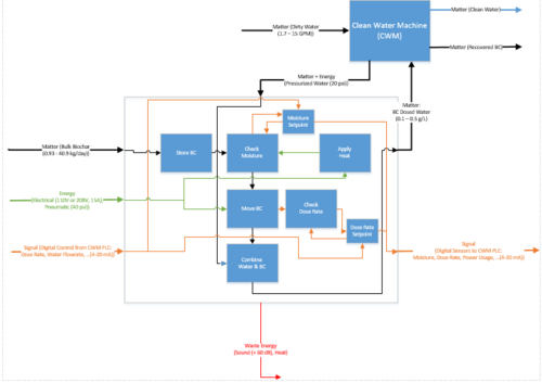
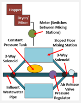
Currently, the BC is dosed into the Clean Water Machine in batches. This requires an operator to manually pour and stir the BC. This is inefficient and does not produce consistent dosing. The flow diagram to the right was provided by our client to describe how the BC can be monitored, dosed systematically, and integrated into the current Clean Water Machine design.
Fluidized Bed[edit | edit source]
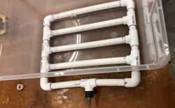
One option explored for maintaining BC consistency was a fluidized bed for drying and mixing. A fluidized bed can produce a liquid effect in granular materials such as sand by distributing air flow from the base of its container. The team constructed a drying mechanism similar to a fluidized bed to test with sand and BC as a proof of concept for this method. PVC piping with 2 mm holes drilled at 45 degree angles 1 inch apart were sealed and connected to an air compressor. Ideally, the air would be heated, and therefore heat the BC while also keeping the powder in motion. However, during the tests with sand, the air flow was not enough to produce the floating effect. The test with BC was even less successful. The design only produced preferential flow in the powder, meaning the air was not distributed throughout the bulk. This was concluded to not be an effective design to reliably treat the BC evenly.
Moisture Content Experiments[edit | edit source]
Experimental plans were written to test the BC density as a function of moisture content. Moisture content is calculated as the percent difference in mass from completely dried BC and the sample at different dry times. During initial testing, the purchased BC was received at around 9% moisture content. We calculated the density to be around 900 kg/m^3. With the density of water assumed to be 1000 kg/m^3, the required moisture content for this system must be under 10% if the dose rate is not corrected for moisture content to remain within 15% accuracy. Otherwise, metering can be corrected for changes in BC density depending on moisture content as output by accurate moisture sensors.
Concepts Considered[edit | edit source]
Pump and auger:
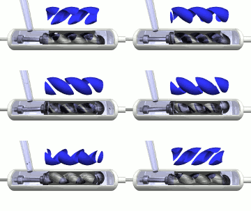
Our clients identified the pumping mechanism as a significant challenge in moving biochar in the past. Because it is a granular material which does not dissolve in water, it often clogged pumps and the small particles cause pump parts to wear quickly or malfunction. As an original solution to this problem, the team considered a design similar to traditional wastewater treatment facilities powder dosing mechanisms. The team toured the the Water Reclamation and Reuse Facility in Moscow, ID, to see how this treatment process dosed powder polymer. This facility used a large auger and large positive displacement pumps, which could potentially be scaled down for our project. Progressive cavity positive displacement pumps are effective with viscous fluids, can produce a constant flow, and has few moving parts that the BC could damage. However, after conducting research into the possibility of scaling down these components, we determined the pump would be too expensive, greater than our $2500 budget, and no auger could be identified that would provide 15% accuracy at this low dose rate.
Valve-controlled semi-continuous flow:
The final version of the team's original suggested prototype is shown on the right. Two parallel sloped floor containers receive BC from the metering system and intermittently dose into the influent pipes to creates a more continuous dosing. This system is also directly in line with the influent water. The BC is dropped into the chamber when both three-way valves are closed. One three-way valve switches the incoming water between the two chambers, and the other three-way valve alternates which chamber is emptied back in line with the pipes. A constant pressure tank and pressure regulator is supplied so that the influent pipe pressure is not altered. However, it was later determined that the flow taken from the influent lines would cause too great a pressure drop from the main line.
Final Design[edit | edit source]
Design[edit | edit source]
Conditioning[edit | edit source]
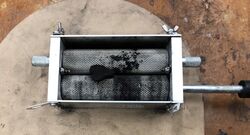
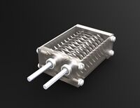
As a solution for the BC inconsistencies in texture and particle size, a grinding system was added to the design below the hopper. Two stainless steel rollers with an adjustable distance between them are attached to a motor at a variable RPM. However during testing, as depicted in the image to the left, larger pieces of BC were not pulled through the grinders. This began clogging the hopper and preventing flow. To solve this problem, a dual milling process was implemented. A similar two-roller system is positioned above the original rollers; larger teeth pulls the BC through and breaks it into smaller pieces, which is subsequently ground to powder in the second step.
Metering[edit | edit source]
To accurately dose biochar, this system receives the water flow rate output from the CWM and uses it as an input to dictate the mass flow rate. From the fluid flow signal, we can find mass flow (g/min) = concentration (g/L) * fluid flow (L/min). From the mass flow rate, we calibrated the motor running the metering mechanism and correlated voltage with the dose rate. See the attached document entitled "Mass Flow" for calculations on the dose rate required for a concentration of 0.5 g/L with a 15% overdose at flow rates between 6-15 gal/min.
Injection[edit | edit source]
The influent water line is pressurized up to 18 psi. A venturi nozzle operates based on a change in liquid pressure when it flows through a constricted space. This provides continuous flow and can be easily adjusted to vary the output. Orignally, this was considered as a dosing mechanism, but through testing, was determined to not be accurate since biochar does not maintain a consistent concentration in a solution. It will instead be installed at the injection location in the system to overcome the back pressure from the transport between atmospheric pressure and pressurized pipes after the BC has been metered. See the attached document "Venturi Calculations" for details on how the correct product was chosen for this application.

Controls[edit | edit source]
- Raspberry Pi 3B+ is the brain of the system. The touchscreen displays sensor readouts and functional warnings. The Pi 3B+ allows for remote connectivity, as it can operate with WiFi with minimal adaption.
- IR distance sensor mounted in the lid of the hopper is connected to LEDs inside the main box. The distance is accurate within 1mm. When the hopper capacity is above 5 gallons, the lights are solid green. When the capacity is between 5-2 gallons, the lights are solid red, indicating a refill. When the BC is below 2 gallons, the LEDs flash red to indicate malfunction.
- 12 VDC 30 RPM high torque motor for the grinders system.
Prototype[edit | edit source]
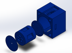
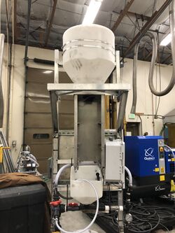
The final built prototype includes a polyethylene hopper capable of storing 3 days worth of BC, secured to the brackets by large clamps. Below the hopper is a stainless steel box containing the dual grinding system and the metering mechanism, with funnels directing the powder flow. The controls box is attached to the side of this box, holding the motors for the grinder and meter. The door of the box has acrylic on the front, sealed with a gasket around the frame, and closes with a latch. The powder then goes through a mix tank, with a nozzle spraying water that creates a vortex at the base. From there, the slurry is pulled through a the venturi nozzle and a static mixer to keep the particles suspended before reaching the rest of the CWM.
Future Directions[edit | edit source]
- Moisture sensors: for a more accurate dosage, we suggest adding more accurate moisture sensors mounted inside the hopper. When the moisture is known, the metering can be corrected for slight differences in BC mass from the difference in density. Additionally, a safe and effective method of drying the BC inside the hopper could be a future endeavor to expedite the process. Any BC over 10% moisture content will not flow through the system well. A dryer and mixer inside the hopper would reduce the risk of clogs or transportation interruptions and make the flow more consistent.
- Gravimetric metering verification: although part of the original design, there is no secondary metering verification on our system. Currently, there is no way to verify that a correct dosage is being applied other than manual testing. Mass turbidity sensors are expensive, so a dry weight verification, such as a load cell, could be implemented to provide error warnings and feedback further down the transport process.
- Remote connectivity: This product design allows for future development in remote connectivity with little to no cost. As described previously, with the Raspberry Pi 3B+, the operator can use the connections already provided on the Pi with a cable to the remote desktop. Further research is required to implement an intranet within the CWM system, but the current computer system is capable of making that adaption.
- Scale up: The system we created is modular and provides a small range of influent wastewater treatment capacity. However, this would ideally be scaled up in the future. Not every component on this system has an appropriate analog for large scale processing. However, many components are custom manufactured, which can be converted to a larger scale. The current process flow would function at any scale, but the physical parameters will need to be reevaluated.
Validation[edit | edit source]
| Requirement | Test | Test subject |
|---|---|---|
| Operating at less than 60dB at full capacity | Use a sound sensor to record a full cycle of the system, and verify signal remains below maximum sound level | Functional prototype |
| 15% accuracy dosing | Have BC dump into separate receptical and weigh on a scale to verify accuracy of dosage dispenser | Functional prototype |
| Must account for variability in BC moisture content | Use a high-accuracy moisture sensor to detect moisture of several batches of BC after processing through system, and compare discrepancies | Functional prototype |
| Must account for variability in BC consistency and texture | Manually, visually inspect BC for clumping and inconsistencies in texture; should be no particles larger than 0.25 inches | Functional prototype |
| Must account for variability in BC dose-rate | Run system through 5 different dose rates, have BC dump into separate receptical, and weigh on a scale to verify accuracy of dosage dispenser | Functional prototype |
| Must account for variability in BC temperature | Use a high-accuracy temperature sensor to detect temperature of several batches of BC after processing through system, and compare discrepancies | Functional prototype |
| Dosage must withstand pressure of 20 psig | Use pressure gauge on output pipe to verify it expels BC mixture at desired pressure | Functional prototype |
| Touch-screen must last 24-hours without recharging | Unplug touchscreen and wait 24-hours; intermittently activate screen (once every 8 hours) to simulate use; after total time period, activate screen and verify use | Functional prototype |
| Must operate within conditions ranging from 20-90% Humidity | Design tests in sealed containers or rooms where humidity level can be adjusted and run system to verify function | Functional prototype |
| Refill no more than once every 3-days | Run system for 72 hours straight with maximum dose-rate and verify that the BC supply will last | Functional prototype |
Team Members[edit | edit source]
| Courtney Wanke
Major: Mechanical Engineering
| |
| McKenzie Walquist
Major: Biological Engineering
| |
| Dylan Kirkpatrick
Major: Biological Engineering
| |
| Phillip Hagen
Major: Electrical Engineering
|
