Bridgeport CNC
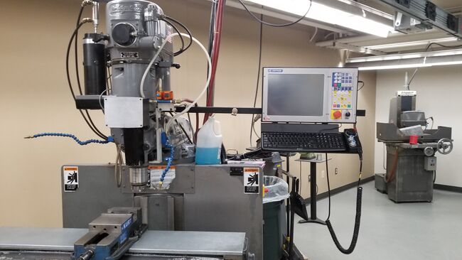
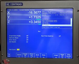
This page is intended to give an overview and basic instruction on the use of the Bridgeport CNC mill.
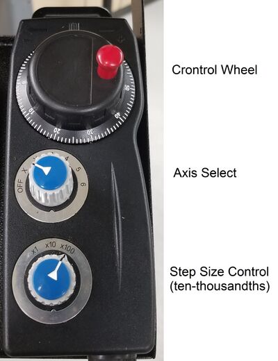
Axis Control[edit | edit source]
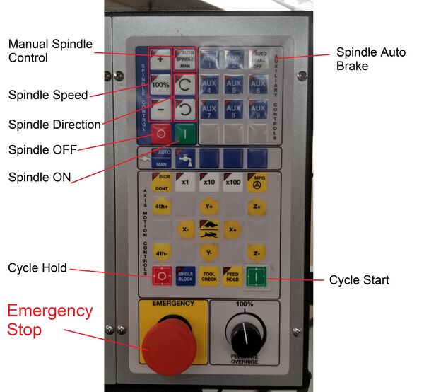
Control Panel[edit | edit source]
Use Auto Spindle Man. to enable manual spindle control
Use Spindle Auto Brake to change tools
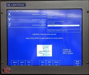
Relevant Menus[edit | edit source]
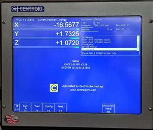
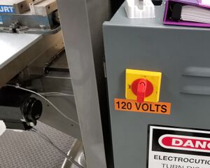
Start Machine[edit | edit source]
1. Turn on main power
2. Wait for control box to boot
3. Press cycle start to home axes
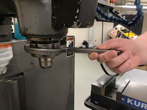
Change Tools[edit | edit source]
1. Turn spindle auto brake on
2. Loosen chuck completely
3. Insert tool
4. Tighten Chuck
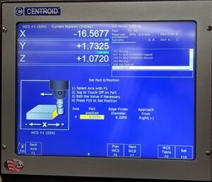
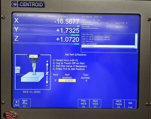
Zero Part X and Y Axes[edit | edit source]
1. Setup Menu > Part Menu
2. Use edge finder to find edge of part
3. Select axis
4. Insert edge finder diameter
5. Select approach direction
6. Set zero
Zero Part Z Axis[edit | edit source]
1. Insert tool #1
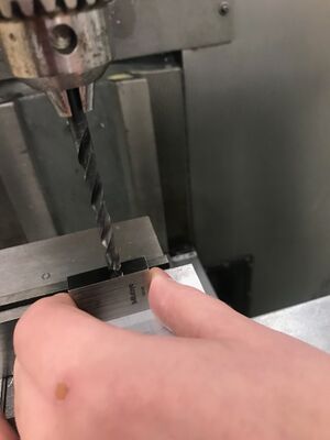
2. Use 1 inch gauge block located on back of mill
3. Lower the tool so the tip touches the gauge block, but the block still slides freely
4. Set offset to 1 inch
5. set zero
Zero Reference Tool[edit | edit source]
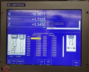
1. Setup Menu > Tool Setup > Tool Library
2. First tool in library will have zero offset
3. Select tool #1
4. Lower the tool so the tip touches the gauge block, but the block still slides freely
5. Move the tool off the part and lower Z axis 1 inch
6. Press Z Ref
Zero Tools[edit | edit source]
1. Select tool
2. Lower the tool so the tip touches the gauge block, but the block still slides freely
3. Move tool off part and lower Z axis 1 inch
4. Press Measure
Load Program[edit | edit source]
1. Insert flash drive with program loaded
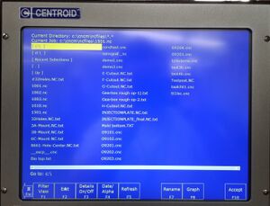
2. Load Menu
3. Select D drive
4. Select Program
Run Program[edit | edit source]
1. Run Menu
2. Search
3. Type 1 for first line of program
4. Press Cycle Start
5. Follow directions for tool change
6. Cycle start after tool change
Shut Down[edit | edit source]
1. Go to Main Menu
2. Select shutdown
3. Select power off
4. Once control box has shut down turn main power switch off
Intercon Conversational[edit | edit source]
What is Intercon: The Intercon software gives operators the ability to create parts and design tool paths at the machine vs using a separate computer. The steps below cover the basics of creating a program file and will also step the user through some of the basic Intercon tools for creating parts.
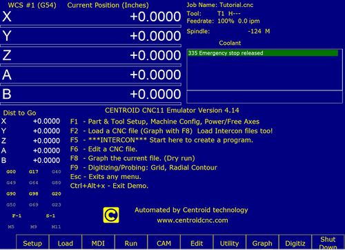
Centroid CNC Mill Main Screen:
You access Intercon through the F5 - CAM option in the CNC software Main screen in the picture below. From here you can select ICN or hit F1 to get to the intercon mill.
Intercon Main Screen
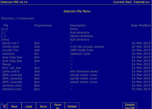
Using Intercon File Menu:
Choosing (F1–File) on the main screen will bring you to the picture below. The files will be saved as .icn and are only readable by Intercon. Select (F1–New) to program a new part. The prompt displayed after clicking (F1-New) allows you to create the name of the new program. Select (F10- Accept) or ENTER key to accept. All other program info (programmer, description, date) can also be entered here.
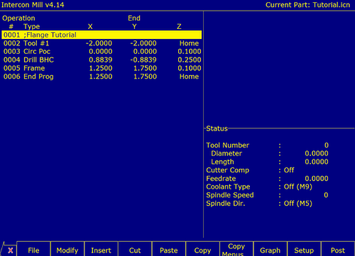
Modify: (F2–Modify) on the main screen allows you to make changes to the selected operation. The operation highlighted in yellow will be selected and a menu will appear that shows the current operation. You can modify the operation as you need in the menu.
Insert:
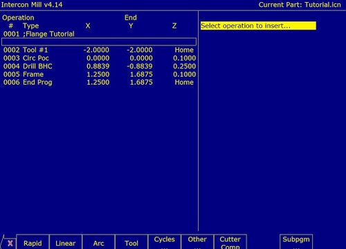
This is where you go to create a new operation. F3–Insert will insert a new operation before the operation that is currently highlighted. Once you hit the insert tool it will bring you to a new menu with several tool options to choose from. The menu is shown below.
- Rapid Traverse(F1) - This tool allows you to change the movement speed of the mill when not cutting. This is useful to reduce the time it takes to create a part.
- Linear Mill(F2) - This tool is used to make straight cuts based on the x, y, and z coordinates you enter. You will have to enter the end coordiates and it will determine the length of angle of the cut for you. This will show up as a line type operation.
- Arc Mill(F3) - This tool is used to make circular cuts. There are four ways to specify your ARC: using an endpoint and a radius (EP&R), using a center point and an angle (CP&A), using a center point and an end point (CP&EP), or using a mid-point and an end point (3- Point). Clicking on the arc type will cycle through them. Once the you have selected the appropriate arc type, you will need to enter all of the informtion highlighted with yellow text.
- Tool Functions (F4) - This tool allows you to change tools for a new operation. The X and Y positions will determine where the tool change takes place. Tool H and D offsets are used to bring up the tool dimensions saved in the library. For example, if tool 1 is a ⅜” end mill, typing 1 into both index boxes will auto fill the tool height and tool diameter to the correct dimensions for the ⅜” end mill. The spindle speed and direction can be changed here and will take effect when the tool change occurs. Coolant can be activated or shut off after the tool change. If this is set to Flood or Mist, the selected coolant system will be started automatically after the tool change. Inputting no for actual tool change is used for when you want to change the tool settings without actually changing the tool. This is useful for when you want to do a finishing pass with the same tool at different settings. Saying yes at the actual tool change will turn off the coolant and stop the spindle.
- Canned Cycles (F5) - This is where you will find tools for drilling, boring, tapping, rectangular and circular pockets, frame milling, threading, and cleanout. Each process has different required inputs, however they are dependent on the part design parameters. For more detailed information on each operation, refer to the manual.
- Subpgm (F9) - Intercon subprograms allow you to make additional copies of a programmed operation. The subprogram has tools to repeat, mirror, or rotate an operation.
Insert Screen
Graph Tool: The graph tool is found on the main Intercon mill menu page. As the steps for creating a part are being programmed into Intercon, the graph tool allows the operator to visually check the tool paths entered as the part is being built. The part can be seen in either 2D or 3D views. Red lines signify Rapid moves, yellow lines represent arc and linear moves, grey lines will signify compensated pass.
Post:
Choosing (F10–Post) when the program is complete will post the current program. By posting the current program, Intercon converts the operations into G-code. Make sure before selecting post to review the tool paths using the graphing tool. After posting, intercon will be exited and the program will be saved.
Additional Intercon Resources:
- Demo software download to complete tutorial: https://www.centroidcnc.com/centroid_diy/centroid_cnc_software_downloads.html
- Software Demo Installation Instructional Video: https://www.youtube.com/watch?v=iOZbF209XpE&feature=youtu.be
- Intercon tutorial Video: https://www.youtube.com/watch?v=mA41pUyONJM
- Intercon tutorial location: The step by step Intercon tutorial can be found on page 10-61 of the bridge port mill CNC manual found in the additional resources sub heading.
- Intercon demo CD location: A CD with the Intercon demo software can also be found in the Mechanical Engineering Machine Shop. Contact Bill for more information.
Additional Resources[edit | edit source]
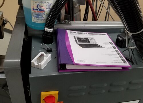
Manual located on back of machine
Centroid CNC Manual PDF Link:https://www.centroidcnc.com/downloads/centroid_v3.16_mill_operator_manual.pdf
