Dilution Tunnel
The dilution tunnel in the Small Engine Research Facility is used to dilute exhaust flow for particulate emissions data. By knowing the dilution ratio of the tunnel, we can calculate actual emissions based on the diluted emissions going through the tunnel. This tutorial explains how to set up and run the dilution tunnel.
Dilution Tunnel Setup and Operation
| Image | Step |
|---|---|
|
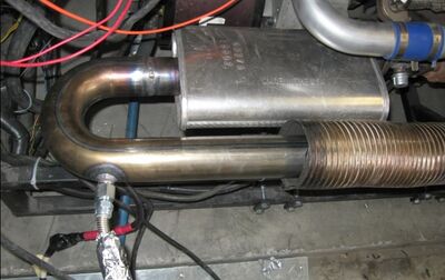
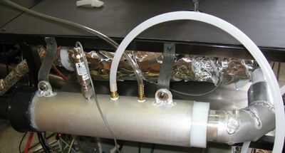
Connect the dilution tunnel inlet line to an exhaust bung. The exhaust bung needs to be a ½ inch NPT male connection welded into the exhaust pipe at least 18 inches before the end of the exhaust pipe. | |
|
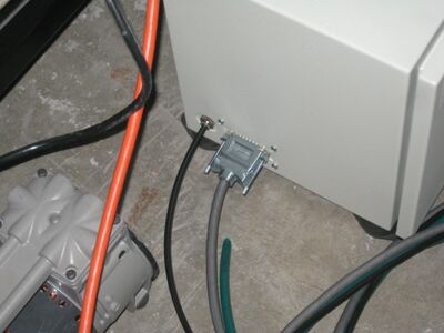
Connect the TEOM sensor unit to the TEOM control unit. This is done by connecting both the data cable and small black tube to the fittings on the side of the sensor unit. | |
|
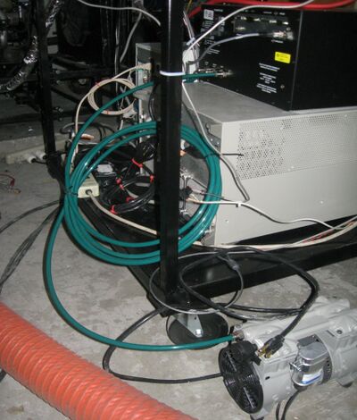
Connect the vacuum pump to the TEOM control unit. This is done by connecting the green tubing to the fitting on the vacuum pump and the fitting on the TEOM control unit. Then turn on the vacuum pump. | |
|
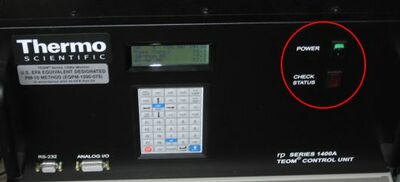
Turn on the TEOM control unit by flipping the front switch. The red check status light will turn on, indicating a temperature problem. This is not a system problem, it just means you will have to wait for the TEOM to warm up and initialize (about an hour). | |
|
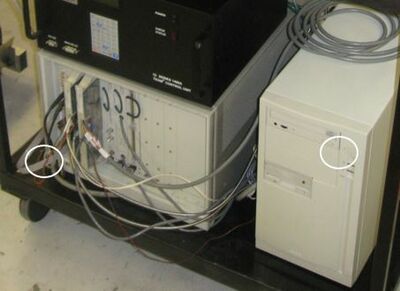
Turn on the HP VXI data acquisition unit and the computer next to it. | |
|
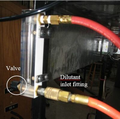
Connect the dilutant supply to the lower fitting on the motive pressure valve. Open the valve just enough to let the air start to flow through the tunnel. | |
|
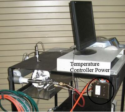
Turn on the temperature controller and set temperature to 820 F. This will correspond to a suction temperature of 700 F. The temperature sensor consistently reads high due to being too close to the wall of the line heater. | |
|
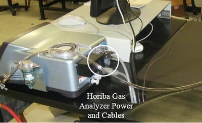
Turn on the Horiba Gas Analyzer. If necessary, connect the cable to the analog out port on the back of the unit. | |
|
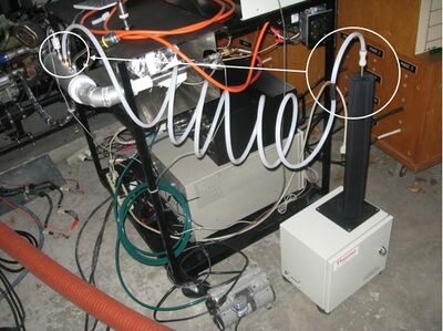
Connect the gas analyzer tubing to the dilution tunnel sampling chamber. | |
|
Connect the TEOM inlet to the dilution tunnel sampling chamber. | |
|
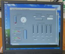
Start Labview and load Dilution_tunnel.VI | |
|
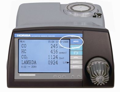
Press MEAS on the Horiba emissions analyzer to start gas measurements. | |
|
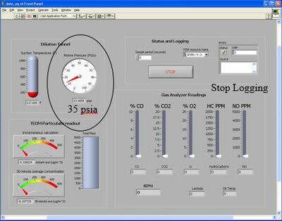
Adjust the valve on the air connection until Labview reads that the Motive Pressure is 35 psia. Then connect the Horiba inlet to the exhaust probe and put the exhaust probe into the raw exhaust stream for a few minutes while the engine is running. Record your CO2 reading. | |
|
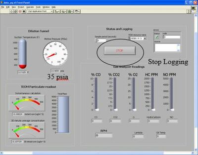
Press Stop Logging in Labview, then connect the Horiba inlet to the dilution tunnel line. Resume logging for a few minutes at the same engine point as before. Record your new CO2 reading. | |
|
You are now ready to start engine testing. Your Dilution Ratio can be calculated using the two previously recorded CO2 readings. This ratio will remain constant throughout testing and will be used to convert from diluted measurements to what your engine is actually outputting. |
