Discount Megamind's Lowcost Electro Encephalogram(EEG)
| Discount Megamind's Lowcost Electro Encephalogram (EEG) | |
| Sponsors | |
| Team Name | Discount Megamind |
| Duration | Fall 2019 - Spring 2020 |
| Faculty Adviser | |
| Mentor | |
| Client | |
| Team Members | |
The goal of the project is, to build a mobile and low-cost electroencephalography(EEG) device to measure brain electrical signals for educational purposes.
Problem Definition[edit | edit source]
Background[edit | edit source]
People know that the heart pumps blood, that the muscles contract, and that the brain thinks. But how does it think and how does it communicate? Currently, if you pulled a random person off the street, and asked how the brain transmitted a signal to the rest of their body, they would probably be unable to answer accurately. The main reason causing this knowledge gap is the inadequate funding and few realistic and engaging ways to illustrate how the brain functions in a traditional school system. Students having minimal knowledge regarding the most critical organ in their body is a substantial problem. This project aims at providing an inexpensive, consistent and easy-to-use solution to this problem. By creating an affordable electroencephalogram system for high school students to build and operate, teachers will be enabled to effectively demonstrate how the brain operates within its physical space.
Deliverables[edit | edit source]
- Improved EEG circuit board
- Using Differential Amplifier
- Arduino-compatible PCB design
- Improved EEG headset
- A more aesthetically pleasing design
- Reduce cost
- Recycled and low-cost materials
- 3-D printing technology
- Document step-by-step video instructions
- On how to build the device
- To present work to Moscow High School
- Add a Graphical-User-Interface
- To allow better data visualization and allow for machine learning analysis of brain waves for data interpretation
Specifications[edit | edit source]
Design Considerations[edit | edit source]
Circuit Considerations[edit | edit source]
Design Background[edit | edit source]
EEG signals are typically around 10 microvolts or less when taken from the exterior skin of the skull. In order to accurately depict these signals, we will need to amplify the signals to levels that would be accessible by our design criteria, an Arduino Uno R3 Microcontroller. By amplifying these signals and attempting to read from an unshielded electrode, we will also need to filter out any unwanted frequencies so that our input data is not construed.
Design Criteria[edit | edit source]
- Target cost under $60
- Amplify signals to millivolt levels (factor of at least 1000 to 10000)
- Use commonly found parts
- Arduino Compatible
- DC Power Driven
- Bandpass 1HZ to ~150HZ
Design 1:[edit | edit source]
Features
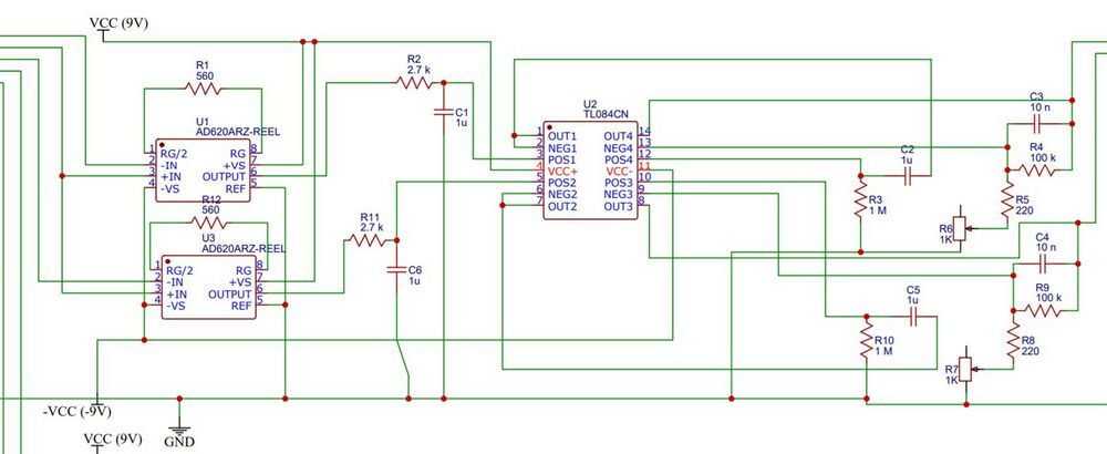
- Using 9V power supply system
- Filtering 1hz to 80hz
- Amplification Gain of 2,000 to 20,000
Issues With Design
- Expensive components (AD620 Amplifier not cost-effective)
- Over amplification on Instrumentation Amplifier introduced excess noise
- Quick power drainage from 9V battery source
Design 2:[edit | edit source]
Features
- Adapted Design to use Arduino Uno R3 Microcontroller
- 5V, lower amperage VDD
- 9V battery and USB compatible
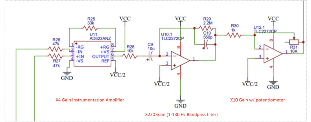
- Filtering 1hz to 130hz
- Amplification Gain of 880 to 8,800
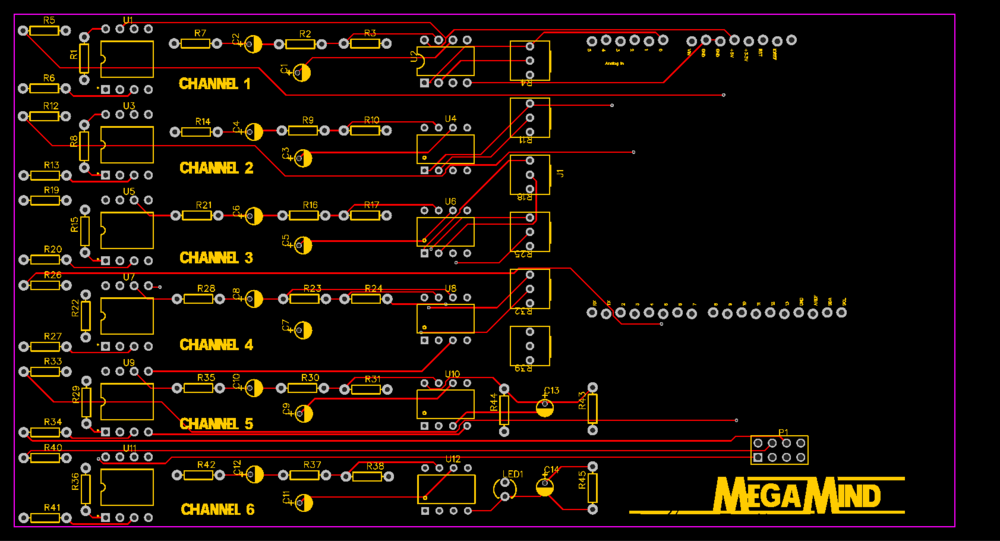
- PCB prototype made
Imporvements
- Lower channel noise
- Significantly lower build cost
- Greater power supply efficiency
Issues With Design
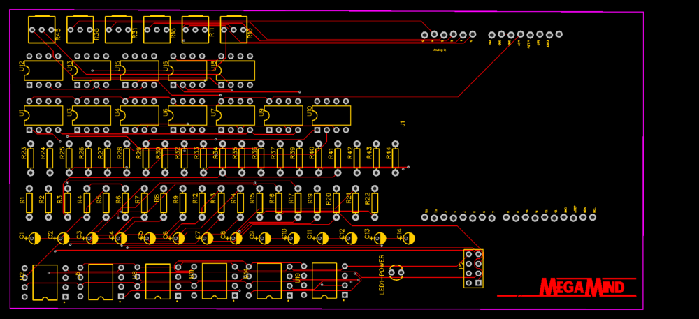
- PCB build used too many Op-Amp DIP-8 chips
- PCB design not intuitive for DIY builds
- Labeling scheme not concise on diagrams
Design 3:[edit | edit source]
Features Features
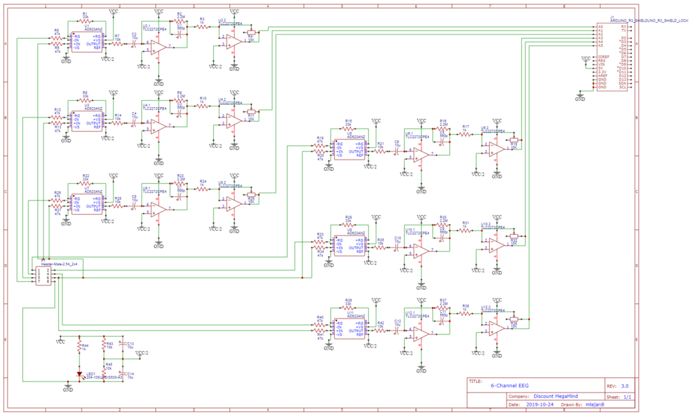
- Adapted Design to use Arduino Uno R3 Microcontroller
- 5V, lower amperage VDD
- 9V battery and USB compatible
- Filtering 1hz to 130hz
- Amplification Gain of 880 to 8,800
- Simplified PCB Design
Improvements
- Fewer components used
- Reduced cost
- Simplified PCB Design Layout
Headset Considerations[edit | edit source]
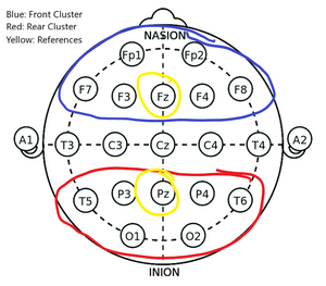
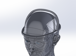
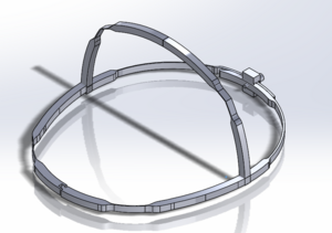
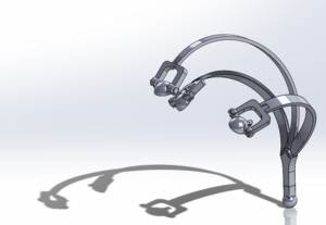
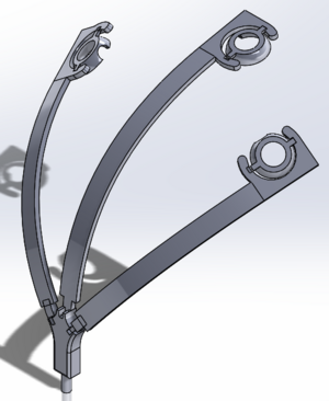
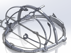
Initially, we printed multiple sizes and fits of the diameter of the headset to find the best shape for a person's head. We also considered different supporting frames to provide the highest amount of stability and chose to go with a frame that rests on the top part of the head. We then tested different mechanisms that affected the diameter size. The final design incorporates a ratchet mechanism that increases the diameter of the headset by 0.75" inches. Next, we determined the best locations to place the electrodes based off the parts of the brain we would like to record data on. The electrode arms were then modeled to reflect these locations. We decided on using a six electrode measuring system, with two arms of three electrodes. This decision was made to keep the overall cost of the device down, while still providing ample area to measure from.
Electrode Placement:
Frame Design 1:
Frame Design 2:
Electrode Arm Design 1:
Electrode Arm Design 2:
Software Considerations[edit | edit source]
The first step we took in designing software for this product was to divide the task at hand into three different segments. The software was divided into: o Arduino and Software Integration o Graphical User Interface (GUI) o A Predictive Machine Learning (ML) Model
Proper integration between the Arduino that is connected to the circuit and a computer that will host the GUI plays a vital role in the rest of the components of the software. Understanding how the data is being sent, what type of data, and considering various baud rates for fast, yet lossless data was our primary target.
On the GUI part, our initial design considerations were to basically pick a technology/language to accomplish the task. We considered .NET Core 3.0 with Windows Forms which would make it way simpler to create Windows applications, vs, Python, which is a versatile language with a lot of libraries and extensive support for ML algorithms.
In order to use machine learning to make guesses about a user's directional thinking or emotional state, sufficient test data needs to be generated so that the machine learning model can be trained. Because there is no identical EEG device to ours out there currently, there is no existing data that our machine learning model can train with. Therefore, creating a data set of brainwave information along with a labeling each sample with the appropriate directional thought or emotional state is necessary to have our machine learning model work correctly. We plan on generating this data set by scanning our team members' brains and applying the appropriate label to each sample. Our plan is to implement this using python using the Keras and Tensorflow libraries.
Project Learning[edit | edit source]
Headset Project Learning
Our main design goals for the headset is to include adjustability mechanisms to allow for the headset to fit a wide range of head sizes.
We initially tried to achieve this goal by changing the diameter of the headset through a pin mechanism located in the back of the headset. This design proved to be hard to adjust, as the error tolerances of the 3D printing fabrication made it difficult to create a perfectly circular shape. This lead to complications in inserting the pin through the holes. It required two people to properly adjust the headset. To overcome this issue, we designed a compliant ratchet mechanism. This allowed for the user to adjust the diameter size of the headset without the help of another person.
Another design we created to provide the headset with more adjustability was to have a ball socket connection between the frame and electrode arms. This design initially worked well, as the ball socket allowed for two degrees of freedom. However, the joint quickly wore out and became loose. This is due to the plastic printing material having a low surface hardness, leading to the joint scrape off parts of the plastic during normal operation. The design we came up with to solve this problem was to create a cylindrical slot in the frame and insert the electrode arm vertically into this slot. While this removed the degrees of freedom for the electrode arms, it provides a stable base. It is also easily moved to the different connection points on the frame.
Electrode and Recording Project Learning
We were able to use the previous group's work as a launching pad for our design and approach. We looked at where the device failed and used a different node placement system that would give us more accurate readings at the specific lobes of the brain. However, this device would be limited to only recording certain parts of the brain at a time instead of the whole brain to keep the project within an affordable price range. In order to compensate for that loss, we were able to develop a modular system that would allow the user to move the nodes to the other part of the head and then undergo the same stimulus to record the previously unrecorded part of the head. Because of this, we have had to develop different stimuli that would trigger different parts of the brain more effectively. After doing research on which lobes of the brain responded to different stimuli and were controlling different functions, we decided on using a puzzle for the occipital lobe, a long division math test for the frontal lobe, an auditory stimulus for the temporal lobe, and touching/texture test for the parietal lobe. In testing the circuit, we attached an electrode to the occipital lobe of our subject and had him work on a puzzle. We were able to record significant changes from when the subject was working on the puzzle vs. when they had their eyes closed.
Software Project Learning
For the GUI, we decided to use Python with the default tKinter library. We decided to steer away from .NET Core specifically because it only allows you to create windows apps, and we found it considerably harder to work with creating ML models in .Net. As far as Python goes, the tKinter library is not a fully fleshed out library for impressive GUI’s but it does the task and is also easy to build ML models. We initially tried to using Keras, an open source machine learning library written in Python, to develop our machine learning model. We later made the decision to switch to developing in C# as it is easier to create a Graphical User Interface with our personnel's experience. Thus, we switched our machine learning library to Keras.NET, the same library as earlier but written in C#. The member in charge of developing the machine learning model uses Ubuntu Linux 18.04 and uses Visual Studio Code as their development environment. There was a unresolvable bug with a dependency Keras.NET needed when trying to develop with it on Linux that halted progress. The next step will be to try finding a C# machine learning that is able to create a LSTM neural network that is able to be developed and tested on Linux. The most promising library we've found at the time is RNNSharp.
Final Design[edit | edit source]
Headset Design[edit | edit source]
Circuit Design[edit | edit source]
Features[edit | edit source]
- Adapted Design to use Arduino Uno R3 Microcontroller
- 5V, lower amperage VDD
- 9V battery and USB compatible
- Filtering 1hz to 130hz
- Amplification Gain of 880 to 8,800
- Simplified PCB Design
Imporvements Over Previous Designs[edit | edit source]
- Reduced Channel Noise
- Amplification levels corrected
- PCB design made intuitive for DIY builds
- Fewer components used
- Reduced cost
- Simplified PCB Design Layout
Software Design[edit | edit source]
For the GUI, we decided to use Python with the default tKinter library. We decided to steer away from .NET Core specifically because it only allows you to create windows apps, and we found it considerably harder to work with creating ML models in .Net. As far as Python goes, the tKinter library is not a fully fleshed out library for impressive GUI’s but it does the task and is also easy to build ML models. We chose to implement our machine learning model using python with the Keras and Tensorflow machine learning libraries. We were able to create an LSTM (Long-Short Term Memory) model with these libraries.
Validation[edit | edit source]
Software[edit | edit source]
Due to unforeseen circumstantial issues with the COVID-19, we were unable to provide a GUI for the project. We did manage to create a few prototypes but couldn't get hands-on with the device. However, we managed to find an open-source software called "Spike Recorder" by Backyard Brains, which had some really good GUI and could be used as a reference by future teams. We were unable to validate our machine learning model as the COVID-19 pandemic wouldn't allow us to collect data from our headset to be able to train our model with.
Team Members[edit | edit source]
| Jeff Courtright
Major: Biological Engineering
|
Michael Lejardi
Major: Computer Engineering
| ||
| Abhilash Reddy
Major: Computer Science
|
Hanieh Nezakati
Major: Electrical Engineering
| ||
| Corbin Schueller
Major: Computer Science
|
Andrew Schultz
Major: Mechanical Engineering
|

