Ergonomic fast battery
|
| |
| Duration: | Spring 2018 - Fall 2018 |
| Team Name | Team chidori |
| Advisor | |
| Team Members: | |
Project overview[edit | edit source]
Background[edit | edit source]
Bicycle dynamos are nothing new, but charge-while-you-ride technology has improved by leaps and bounds in the last few years.These days you can charge just about any device that uses USB power using your own physical exertion, including smartphones, tablets and rechargeable lights.
Problem Statement[edit | edit source]
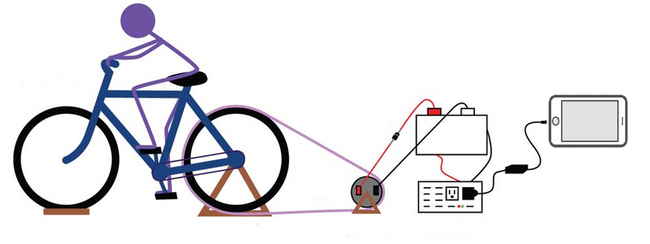
The intention of this project is to build a straight forward human powered generator from a used bicycle and use it to charge our phone. This project help us develop engineering skills while learning about a clean way of generating electricity.
Deliverable & Specifications[edit | edit source]
1.Charge smartphone fast.
2.Portable and reliable cel1phone charging
3.Ensure enough power and steady voltage.
Goals[edit | edit source]
designing a phone charge that uses power generated from the bicycle. A normal phone usually use 5V charge and a USB. So our goal is to able generate electricity from the bicycle that can give an out put of 5V by using a USB output. As a group project, we have pinpointed our design constraints, we divided the project as 3 parts: generator, DC-DC converter(to constant the variable input), battery. And we will focus on designing the DC-DC converter.
Budget[edit | edit source]
Design[edit | edit source]
System Diagram[edit | edit source]
Important Using Devices[edit | edit source]
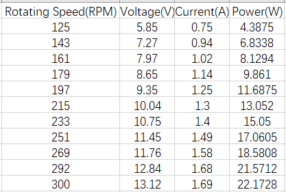
| we choose a 24V 600rpm 100w AC permanent magnet generator. The ratio of rotating speed and voltage is constant. However, it's an AC generator, we need to use an AC-DC converter. The work region for riding a bicycle is 0-300rpm, so the generator can output 0-12v voltage. | |
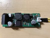
| We use this AC-DC converter pcb board to get a fixed voltage DC current.And it's input work region is 5.5v-16.5v and the output is 15v. | |
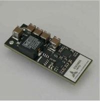
| To charge the capacitor, we need constant current. We use a buck converter as a current rugulator.For this, it's output can be control.
Input Voltage: DC 12V Input Current: 1.45-4.167A Output Voltage: 2.5-7.14V Output Current: 7A(fixed)
| |
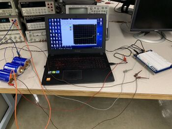
| This capacitor is super-capacitor, it has a large capacity, but it can't load a high voltage. We use a combination of several super-capacitor serious connections to get a high capacity and load the voltage we need.
3 capacitors in series. Total C=500F Total Vdc=8.1V Effective energy storage 3.5w·hr Maximum energy storage 4.5w·hr | |
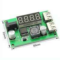
| we use a buck converter to output constant 5V,3A. It means we can charge 2 phones at same time.
|
Circuit Design[edit | edit source]
Testing[edit | edit source]
Generator Testing[edit | edit source]
|
For this testing we would like to check generator's output capability. This generator don't give us expected power output in our system working region. Fortunately, the output power is also accepted. |
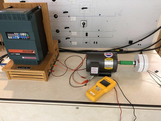
We use a motor to drive our generator for testing. |
Current Regulator Testing[edit | edit source]
The dc-dc converter work as a current regulator to charge our capacitors. For this current regulator, an SPI slave port is provided to allow a host to configure its output limits and enables. So, we select using an Arduino to drive it, and we could get any voltage and current output in its working region.
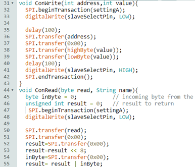
This is our coding loop,we communicate with the current regulator by arduino.
|
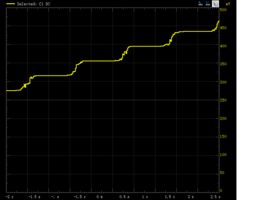
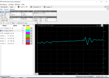
The capacitor charging plot |
Current(fixed) output from current regulator |
Capacitor Testing[edit | edit source]
| We use an unstable volatge supply to simulate the bicycle generator output, and this is the plot of the input power,(W-t diagram) |
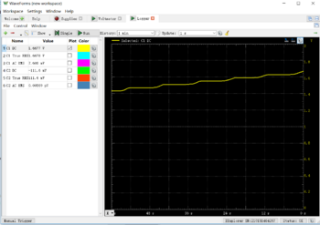
We test the voltage in the cap combinations, and this plot is the V-t diagram of the voltage in the caps |
|
|---|
Team Information[edit | edit source]
Members
| Chensheng Zhu electrical engineering |
Meiyuan Zou electrical engineering |
Chenghao Shi electrical engineering |
|---|---|---|
| Bio: Chensheng zhu is a senior in Electrical engineering looking at graduate in December 2018 from the University of Idaho. His favorite sports are basketball. The most favorite of the project has been learned more about how to control the circuit. After graduating he plans he plans on going to study Master's degree. |
Bio: Meiyuan Zou is a senior in Electrical Engineering. He is looking to graduate in December 2018. His favorite sport is basketball. His hobbies are travel, watching movies and playing video games. After graduating from the UI, he plans on going to study Master's degree. His favorite aspect of the major is about power. |
Bio: Chenghao shi is a senior in Electrical engineering looking at graduate in December 2018 from the University of Idaho. His favorite sports are basketball and hiking. The most favorite of the project has been learned more about how to get stable voltage. After graduation, he plans on an internship at a power company. |


