Low-Cost, Controllable Hypoxia Chamber
| [[File:|300px|center|alt=]] | |
| Sponsors | Dr. Nate Schiele |
| Team Name | HYPEngineers |
| Duration | 2020 - 2021 |
| Faculty Advisor | Dr. Dev Shrestha |
| Mentor | Ian Glasgow |
| Client | Dr. Nate Schiele |
| Team Members |
|
Problem definition[edit | edit source]
The aim of this project is to design and construct a low-cost, controllable hypoxia chamber for stem cell research. The results from this project will be published in an open access journal.
Background[edit | edit source]
A crucial component to conducting stem cell research is maintaining a hypoxic growing environment. Stem cells naturally grow in a low-oxygen environment and simulating this environment during experiments allows researchers to more efficiently cultivate stem cells and conduct research regarding the effect of low-oxygen environments on the cells’ development. A hypoxic environment can be simulated by using cobalt chloride, but this has undesired side effects on the cells’ health. A more realistic and effective solution is to cultivate the cells in a hypoxic chamber. However, current commercial hypoxia chambers are expensive. The objective of this project is to develop a functional, simple, and low-cost hypoxia chamber for stem cell research. The results of this project will include the hypoxia chamber design and physical product as well as a published paper detailing our design and construction process. This will allow other researchers to utilize our technology and ideas.
Deliverables[edit | edit source]
The final deliverables for this project will be a functional, controllable hypoxia chamber that cost less than $1000 dollars to build. The chamber will fit inside a standard size incubator and function within the incubator environment. It will be capable of maintaining hypoxic conditions for minimum periods of 21 days, also safe for sterilization and reusable for multiple experiments. The chamber control system will be controlled through a GUI, where the user can customize the O2 and CO2 gas levels as well as monitor the current chamber conditions and save the data to a CSV file.
Specifications[edit | edit source]
Chamber specifications:
- Must be capable of controlling oxygen levels between 1% and 21%.
- Must be capable of maintaining carbon dioxide level at 5%.
- Control system for chamber will have an operational voltage of 5V.
- Chamber components must withstand temperatures of up to 50 degrees Celsius and a humidity level of 85-95%.
- At least four 13cm x 9cm x 2.5cm well multidishes must fit inside.
- The chamber should be easily portable.
- When closed, it should be airtight for ease of maintaining hypoxic environment.
- Final product should be transparent so that well multidishes are visible.
- Total cost of chamber and manufacturing must not exceed $1000.
Design considerations[edit | edit source]
When designing the chamber, the following must be taken into consideration:
- Materials used must not affect culturing of stem cells.
- Door opening must be large enough to move well multidishes in & out safely
- Pressure must not be able to build up within chamber
Design development[edit | edit source]
This section details the design development for the various components of our system. The information in each sub-section is presented in chronological order so that anyone can see the progression of our ideas over the course of the project.
Chamber from scratch[edit | edit source]
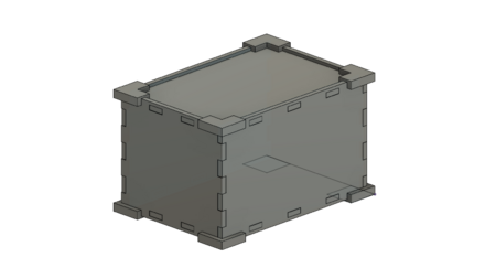
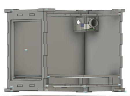
One initial idea we had for the chamber was custom designing a box using a modeling software. This would allow us to tailor the design of the chamber to our needs. This design would be constructed by cutting sheets of a hard plastic and using epoxy to adhere the chamber along the edges.
| Figure | Description |
|---|---|
|
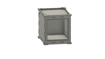
This is the intial design for the custom designed chamber option. At this point, no decision had been made as to how a door would be incorporated into the chamber. For this design, we are planning on using acrylic for the chamber walls to allow transparency. There will be 3D printed bottom supports made for the chamber. | |
|
The dimensions for this chamber design, measured from corner to corner are(L x W x H): 9.68 in. x 6.81 in. x 5.812 in. The walls are 0.25 in. thick. | |
|
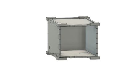
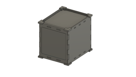
This is the updated design idea for the custom chamber design. The overall dimensions for this design were increased to allow more space for components inside the chamber and a door. The door will be completely removable, we plan to add a handle and latches to the door. There will be an o-ring around the door to create an airtight seal. Holes will be added to the side of the chamber for the gas input and output as well as the sensor wiring. | |
|
The dimensions for this chamber design, measured from corner to corner are (L x W x H): 12.25 in. x 10.02 in. x 10.74 in. The door & front panel of chamber thickness was increased to 0.5 in. for ease of manufacturing purposes. | |
|
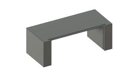
In order to maintain proper humidity within the chamber, it is necessary to have a tray of water inside the chamber. Therefore, a shelf to separate the cell plates from the water tray is necessary. This is the intial design idea for the shelf. The water tray would sit below the shelf, and a piece of wire mesh would be placed into the grooves to cover the water tray while allowing the water vapor to permeate the chamber. The dimensions for this shelf design are (L x W X H): 4 in. x 9 in. x 3.25 in. | |
|
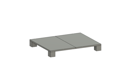
In this updated design for the shelf, the length was increased to give greater surface area for tray of water, and height was reduced so that it takes up less space. Supports for the shelf will be fixed to the inside of the chamber, while the shelf pieces themselves will be removeable to access the tray of water. The shelf pieces will have small holes/slits in them to allow for circulation of the humidity. The dimensions for this shelf design are (L x W x H): 10.65 in. x 8.8 in. x 1.25 in. | |
|
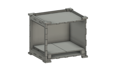
This is showing the shelf placed into the updated chamber design. The shelf now runs almost the entirety of the bottom of the chamber. |
Pre-built chamber[edit | edit source]
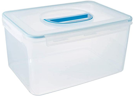
Another idea we had for the design of the chamber was to purchase a pre-made container that we could modify to fit our needs. This idea is a good option as it is cheaper than buying acrylic and cutting it, and the pre-made container would be guaranteed airtight.
| Figure | Description |
|---|---|
|
This is an image of the plastic container we plan to use for this design. It will be cheaper and easier to manufacture than creating a custom design chamber. | |
|
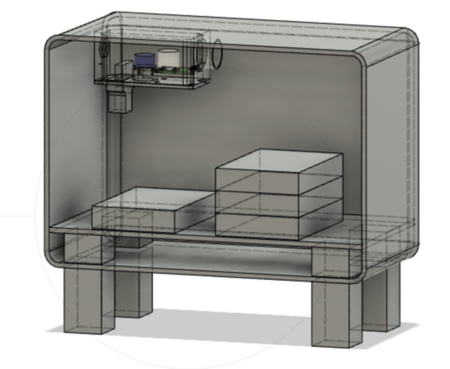
This is the initial design for the premade chamber. The support stilts and the shelf supports will be 3D printed. The shelf covering the water tray area will be made from sheet metal. Sensors & housing will be mounted in the back left upper corner. | |
|
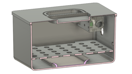
This is the finalized version of the pre-made chamber design. In this design, the chamber was turned right side up so that the lid would be easier to put on and take off. There is no longer a need for support stilts for the chamber since it will sit evenly right side up. |
Control system[edit | edit source]
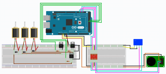
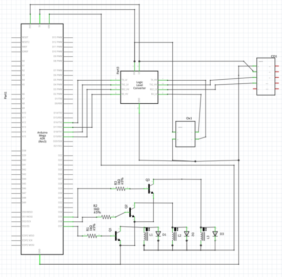
The control system consists of an O2 sensor, a CO2 sensor, and three gas solenoids, two of which input O2 and CO2 into the system and the other exhausts gas out of the chamber. The sensors will be mounted inside the chamber to monitor the conditions, which are sent to the microcontroller via serial communication. The solenoids are then opened, if needed, for the appropriate amount of time necessary to reach and maintain the desired chamber conditions. The system relies on a PI controller to avoid overshoot while reaching the O2 and CO2 setpoints.
| Figure | Description |
|---|---|
|
On the left side, solenoids are connected to diodes, BJT transistors, and resistors, and then finally to the microcontroller. The solenoids control the gas input/output tubes. The diodes ensure that the solenoids don't send a current spike back through the circuit when they turn off. The transistors ensure the Arduino can control the solenoids, and the resistors limit the current so that the transistors don't burn up. On the right side, the oxygen (blue) and CO2 (green/black) sensors are connected through an adapter board to the microcontroller. Both sensors operate at 3.3V for their serial (Tx/Rx) communications, while the Arduino operates at 5V. The adapter board allows this communication to function by level shifting the signals. | |
|
This is a basic level schematic of the circuit. The microcontroller is seen on the right, the solenoids and their components are in the middle of the schematic, and the sensors and adapter board are on the bottom right. | |
|
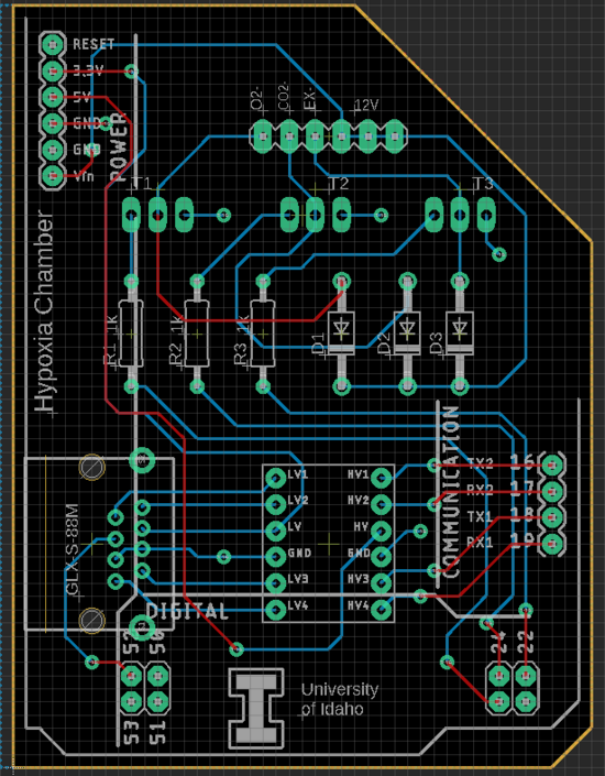
In order to reduce the amount of wiring needed for the control system, a custom PCB was designed to attach directly to the microcontroller. This is the schematic for the custom PCB. | |
|
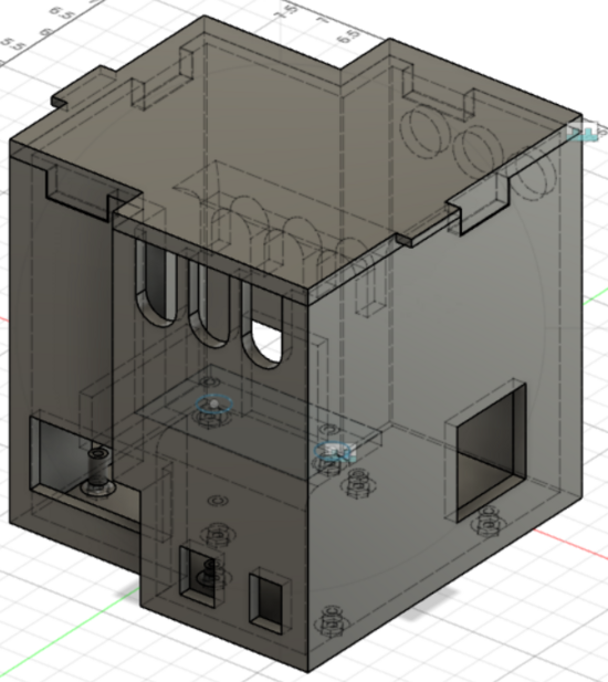
To provide protection to the microcontrollers and gas solednoids, a housing was designed to contain them. This housing will make the system more organized and offer a rigid contianer for the essential components of the control system. This is the deisgn of the electronics housing. |
| Figure | Description |
|---|---|
|
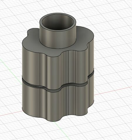
This was the first model for the sensor housing. It is designed to be form fit around the sensors. The top will have threads for a filter cap to isolate the sensors because they can not be cleaned using ethanol. The fitting is split into two pieces to be able to insert the sensors and wire them and then combine it together. This was intended to be attached to the outside of the chamber with the filter cap inside. | |
|
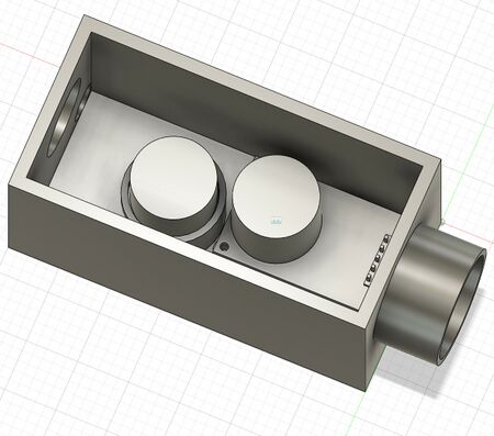
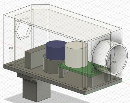
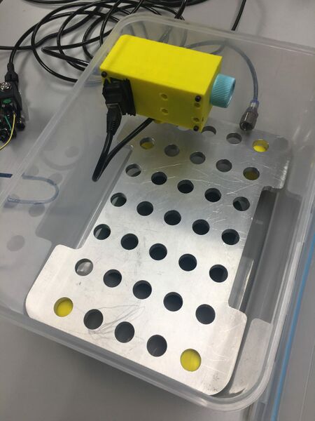
This is an updated model of the sensor housing after realizing we needed a PCB for the CO2 sensor. The housing has mounting points for the board as well as a holder for the O2 sensor that allows access to the wiring. The filter cap portion remained the same, except that now the whole housing is desinged to fit inside the chamber. The exhaust port for the hypoxia chamber was moved into the sensor housing to force airflow over the sensors. | |
|
This updated model for the sensor housing was very similar to the 2nd model, however, it was modified to be more workable. The bottom portion that the sensors attach to is now removable that way the upper portion can be attached to the Hypoxia chamber. The exhaust hole was shaped to fit around the bulkhead air fitting to get a tighter seal. The wires are designed to come out of the bottom of the housing using an RJ45 Adapter so when the bottom plate is removed they do not get left inside the housing. | |
|
This is a model of the sensor housing mounted into the upper corner of the hypoxia chamber. | |
|
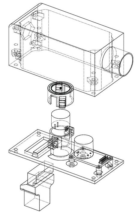
This is a schematic of the final design for the sensor housing that has been expanded to show how the sensors will be placed into the housing. The CO2 sensor (right) will be mounted on a PCB that is secured to the sensor housing, and the O2 sensor (left) will be placed into a small port and covered by a secured cap. |
User interface[edit | edit source]
| Figure | Description |
|---|---|
|
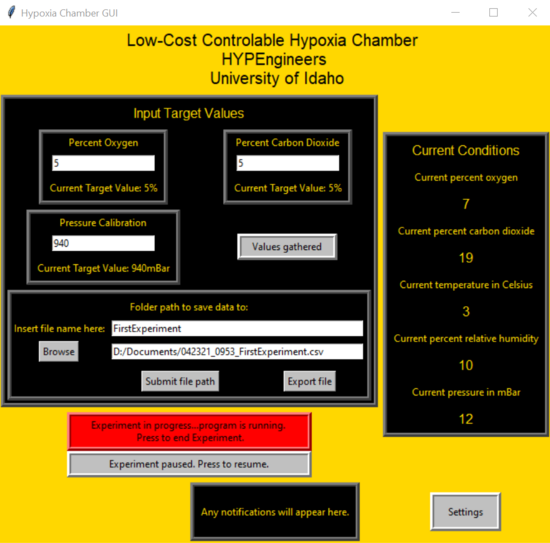
The user interface for this system was created using python and it runs on a raspberry pi that is connected to the mega microcontroller. There is a button on the interface where the user can click to connect to the microcontroller. The Through the UI, the user can set custom O2 and CO2 setpoints, and monitor the O2%, CO2%, temperature, humidity, and pressure within the chamber. There is also a place to select a CSV file to save experiment data to. Once the desired setpoint values have been entered, the experiment can be started by pressing the “Begin Experiment” button. If, at any point, the chamber needs to be opened during an experiment, there is a button to pause the system to avoid wasting gas. The experiment can easily be resumed using the button after the chamber is resealed. If the user finds they need to adjust the PI control for the system, there is a button which will open a window where the PI values can be adjusted. The settings for the PI control can be saved, so that the settings will stay at the adjusted values for future experiments. |
Prototypes[edit | edit source]
Chamber from scratch[edit | edit source]
| Figure | Description |
|---|---|
|
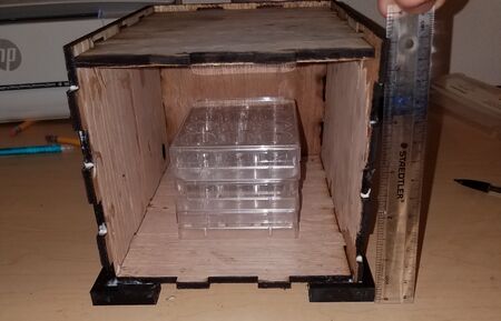
This is the first construction of the custom chamber design. It was made using laser cut wood and wood glue. The purpose was to have a prototype of our design idea for the first project snapshot. | |
|
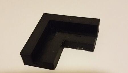
This is one of the 3D printed corner pieces. The purpose of these pieces is to provide support and structural stability to the chamber. |
| Figure | Description |
|---|---|
|
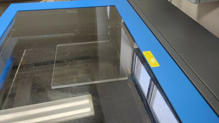
The manufacturing process for the second custom chamber prototype began with laser cutting acrylic pieces. This image shows the acrylic inside the laser cutting machine. | |
|
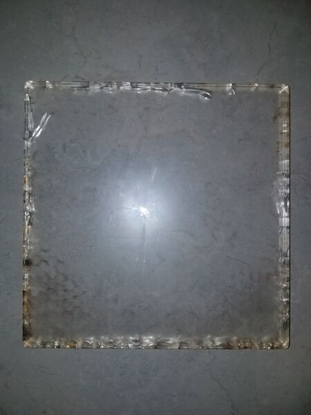
After the acrylic was laser cut we attempted to clean the acrylic with ethanol, the solvent which will be used for sterilization in Dr. Schiele's lab. Upon applying the ethanol to the acrylic, however, we discovered that ethanol causes crazing to occur within the acrylic which can impact the structural stability. Due to this unforeseen issue and time/cost restraints, we decided it was in out best interest to stop working on the custom chamber design option for the time being and focus our efforts on the pre-made chamber design. |
Pre-built chamber[edit | edit source]
| Figure | Description |
|---|---|
|
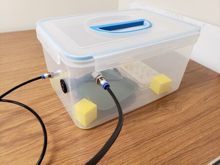
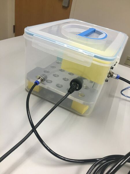
The manufacturing process for the first premade chamber prototype began with drilling holes for the through wall fittings. After drilling the holes, the through wall fittings were inserted to ensure the holes were made properly. This image shows chamber with the through wall fittings in place, as well as the humidity tray, shelf supports, and a well plate inside. | |
|
Shelf sitting inside chamber with the sensor housing mounted in the upper corner. |
Control system[edit | edit source]
| Figure | Description |
|---|---|
|
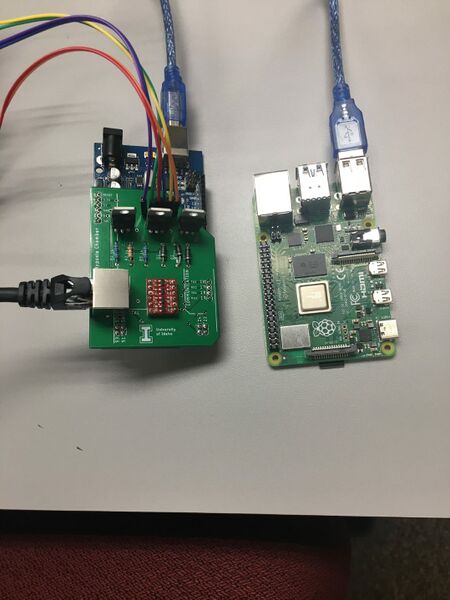
Pictured here are the two control system microcontrollers, a Raspberry Pi and Elegoo Mega, with the custom PCB attached to the Mega. The next goal for the control system will be to design an electronics housing that will contain the microcontrollers as well as the three gas solenoids. This will provide protection for the crucial electronics components and some organization for the control system. | |
|
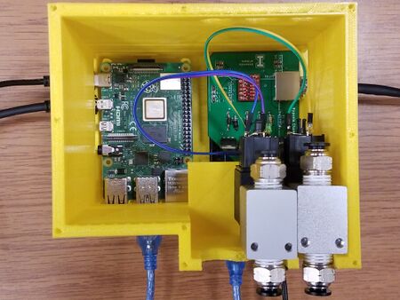
This is a picture of the microcontrollers and solenoids placed into the the housing. The raspberry pi, mega microcontroller and PCB are placed into the bottom of the housing, and the solenoids are resting on a shelf on the side of the housing. There are holes in the housing to allow access to the ports on the raspberry pi and mega microcontroller. There is also a lid that is placed on top of the housing to make it a contained unit, but the lid is not pictured here as it needed to be reprinted. |
Final product[edit | edit source]
| Figure | Description |
|---|---|
|
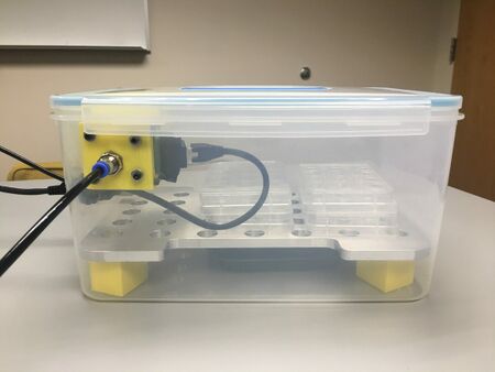
The final product design. In this design, there is a water tray placed in the bottom of the chamber. Four supports in the bottom corners of the chamber hold an aluminum shelf that covers the water tray. As shown in the picture, the cell culture plates are placed on top of the shelf. The 3D printed sensor housing is mounted in the upper corner of the chamber. |
Validation[edit | edit source]
Chamber testing[edit | edit source]
| Figure | Description |
|---|---|
|
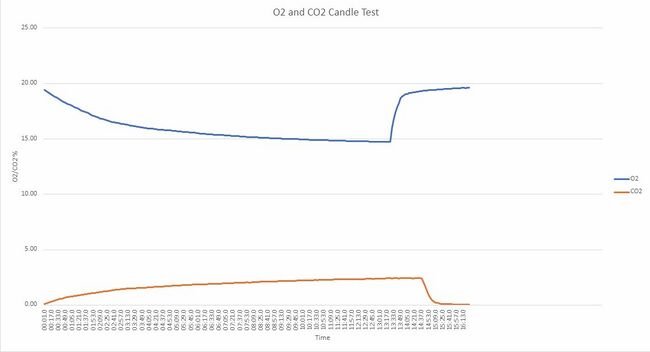
To test whether or not the sensors we got were working properly, we placed the O2 and CO2 sensors into a box with a candle inside. The candle was then lit, and the lid to the box closed. The idea was to see if the sensors would track the change in O2 and CO2 in the air as the candle burned. The results of the test show that the sensors accurately tracked the lowering O2 and rising CO2 levels within the box over time. |
| Figure | Description |
|---|---|
|
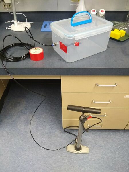
To test whether the chamber had any leaks in the areas where through wall fittings were placed, we used soapy water and rubbed it around the fittings. After applying the soapy water, the chamber lid was sealed and we began to slightly pressurize the chamber using a pump. We observed the areas with soapy water, any bubbles appearing in these areas would indicate a leak from the chamber. We saw no bubbles form after the chamber was pressurized, so we concluded that the chamber was still airtight post-modification. However, we noticed that if the chamber became too pressurized, that would cause the lid to bulge upward and separate slightly from the chamber creating a leak. This will not be an issue in the future, as the chamber will not be pressurized when in operation. | |
|
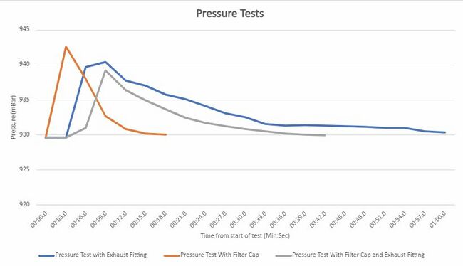
After it was determined that the system was airtight, we wanted to evaluate the airflow through the chamber. Specifically, we were testing whether placing a filter cap over the exhaust fitting would significantly impede exhaust airflow. The chamber was slightly pressurized using a pump, and the pressure was recorded over time. This was done once with just the chamber exhaust fitting in place, and once with a filter cap placed over the exhaust fitting. The results from this test showed that the filter cap did not significantly affect the exhaust airflow. |
| Figure | Description |
|---|---|
|
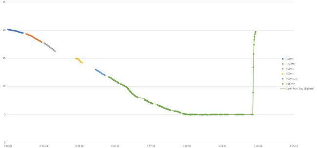
This was the first test to determine if our control system could reach an O2 level of 5% using just nitrogen gas. After the test began, some edits were made to the control system code to change the amount of time the solenoid was releasing gas into the chamber. The results from this test showed that the system successfully reached and maintained the O2 setpoint. The setpoint was reached in approximately one hour and ten minutes. |
| Figure | Description |
|---|---|
|
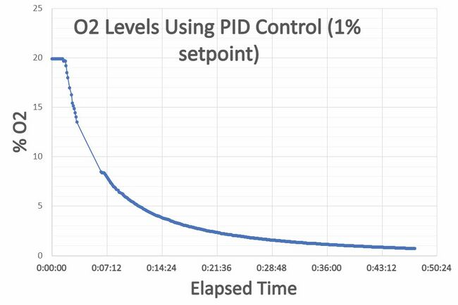
This test was to determine whether a PI control system would be better for reaching the O2 setpoint. The PI control should reduce any overshooting of the setpoint. The results from this test showed this system was greatly improved from the previous test. The chamber reached a setpoint of 1% O2 in approximately 38 minutes. However, the setpoint was still initially overshot before it became steady. Some edits to the PI control are necessary to ensure no overshot in the future |
| Figure | Description |
|---|---|
|
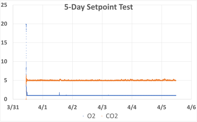
To determine the long-term performance of the chamber, a test was run over the duration of 5 days. For this test, both the nitrogen and carbon dioxide gasses were connected to the chamber. The goal was to have the system reach setpoints of 5% CO2 and 1% O2. The results from this test showed that our system was capable of reaching and maintaining the desired setpoints for long periods of time. However, there are still some kinks to work out in the control system to reduce the fluctuations in CO2. Also, after this test we discovered that the exhaust solenoid had been leaking, so we will replace it with a new one. |
| Figure | Description |
|---|---|
|
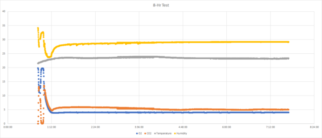
After adjusting the PI control system, this test was run to evaluate the performance of the chamber. The setpoints were 5% CO2 and 4% O2. The system was able to reach the desired setpoints and maintain the hypoxic environment. |
| Figure | Description |
|---|---|
|
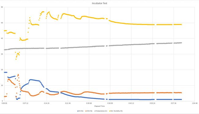
This test was performed in order to evaluate how the chamber operates while inside the incubator. The water tray in the bottom of the chamber was filled to provide humidity, and the aluminum shelf was put in place over the tray. During the beginning of the test, the exhaust and input tubes were accidentally connected in swapped spots, which explains the large fluctuations toward the beginning of the graph. After this was discovered, the tubes were placed in their appropriate spots. The results from this test showed that the chamber will maintain the proper incubator conditions alongside a hypoxic environment. Ideally, before a future test is run, the user will place the chamber without the lid into the incubator for a period of time before the test to allow the chamber to come to incubator conditions. |
Final deliverables[edit | edit source]
The final product of this project is a functional, low-cost and simple to manufacture hypoxia chamber. The cost of all components used for this project totaled $783.98. The chamber is capable of maintaining variable O2 levels of 1% to 21% and a CO2 level of 5% for extended periods of time. The chamber fits within a standard sized incubator and operates within the incubator environment. The O2%, CO2%, temperature, humidity and pressure conditions within the chamber can be monitored from a simple user interface. The UI is also where the O2 and CO2 setpoints can be customized, and the user can set a CSV file to save experiment data to.
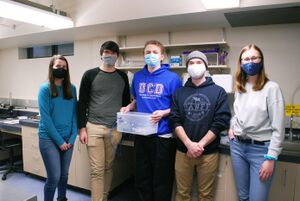
Team members[edit | edit source]
| Andrew Hartman
Major: Electrical Engineering
|
Jacob Knudson
Major: Biological Engineering
| ||
| Colin Marchus
Major: Biological Engineering
|
Alexandra Morrison
Major: Electrical Engineering
| ||
| Isabell Strawn
Major: Biological Engineering
|
Additional Documentation[edit | edit source]
Budget
File:Hypoxia chamber budget.pdf
Design Validation Plan
File:Chamber Design Validation Plan.pdf
GitHub Repo
Project Portfolio
Presentations
File:Capstone Snapshot -2 Poster HYPE.pdf
File:Final Engineering Release Review HYPE.pdf
File:Capstone Snapshot 3 Poster HYPE.pdf
File:Expo Technical Presentation HYPE.pdf
Project Schedule
