Part Design (MakerBot)
Main Article: 3D Printing
Before printing parts on the MakerBot, the parts must be designed to meet the geometric and building constraints of the machine. This includes matching the machine's tolerance capabilities, shrinkage/expansion, accomodating for hole precision, and building arches and overhangs with supports or fillets to avoid sagging.
Machine Limitations[edit | edit source] | |
| MakerBot has specific tolerances that need to be met in order for the part to be printed correctly. All finished parts will have a variance on the X, Y, and Z axes. There will be a 0.3% variance in the X axis , 0.2% in the Y axis, and 0.4% in the Z axis. Parts should be designed bigger/smaller and machined to tolerance if accuracy is necessary.
In addition, MakerBot has a minimum layer height of 0.1 mm. The layer height can be adjusted accordingly for the part that is being printed. NOTE: As the nozzle moves further away from the center the part will become less accurate. Build Volume[edit | edit source]Parts cannot exceed 11.2 L x 6.0 W x 6.1 H in. This is the maximum print size MakerBot can print. Minimum Extrude Tolerance[edit | edit source]MakerBot is unable to print parts (or parts that have features) that have a diameter of 3/32" or smaller. Minimum Wall Tolerance[edit | edit source]When designing cuts into parts, the cuts need to be placed a minimum of 1/32" away from the wall. If it the cut is too close to the wall it will cause deformation. |
|
Overhangs and Arches[edit | edit source] | |
| Overhangs and arches larger than 1" will sag because there is no material supporting them. Selecting rafts/supports when generating the MakerBot code will add rafts and supports. Rafts/supports should be avoided when printing parts that contains circular edge(s) on the base plate because MakerBot will fail to print parts using its standard supports and rafts feature. For arches and overhangs at 90º, a fillet can be added to prevent sagging. Alternatively support material must be designed onto the part in the 3D design program. | |
Edges[edit | edit source]All outside edges automatically have a rounded edge of 3/32". This is due to the size of the filament when it is being extruded. Hole Design[edit | edit source]When printing a part that contains a hole design in it, set the shell thickness to '2' and make the hole 0.005" smaller in the 3D design program. After the part is printed, the hole can be drilled to size. Refer to Drilling and Tapping for drilling recommendations. Edges Touching Base Plate[edit | edit source]Edges that are touching the base plate cannot come to a peak on the base plate, they must be at least 3/32" wide to avoid print failure. | |
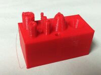
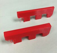
Built Parts Analysis[edit | edit source]Here is an analysis of some test prints that were used to determine content for this page: Built Parts References[edit | edit source] | |


