Small Satellite Technology
| Small Satellite Technology | |
|---|---|
| An proof of concept senior design project | |
| Sponsors | NASA Jet Propulsion Labratory
NASA Idaho Space Grant Consortium
|
| Team Name | Pantheon |
| Duration | Fall 2013 - Spring 2014 |
| Faculty Advisers |
|
| Mentors |
|
Small Satellite Weather Balloon Technology Design Project
Project Goal
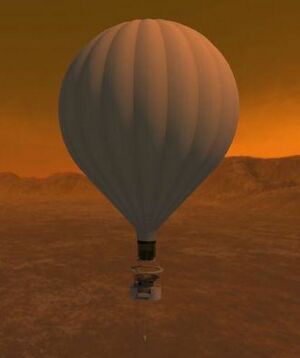
To demonstrate a proof of concept for a radio science technique to measure the dynamics of a planetary atmosphere using a capsule in flight. [pantheondesignproject.wordpress.com]
Project Background
An important measurement in the study of planetary atmospheres is the profile of wind speeds from the upper atmosphere to the surface. Entry and descent probe measurements of the winds of Venus, Jupiter, and Saturn’s largest moon Titan have been made by Doppler tracking of Pioneer and Venera probes, the Galileo probe, and the Huygens probe, respectively. The winds in the upper atmosphere of Venus were also measured by tracking the Soviet VEGA balloons. The most significant shortcoming to these measurements is that they provide one profile of winds at a single location. The dynamics of planetary atmospheres can be better characterized if the winds are measured simultaneously at multiple locations. One concept for doing this is to have a single ground station such as a planetary lander that would release multiple balloon-borne transceivers that continuously transmit to the ground station. By making precise frequency measurements at the ground station of the signal from each balloon capsule in flight, the Doppler shift of the signal can be used to provide an accurate measurement of the balloon dynamics and from this the wind dynamics can be inferred.
Project Goals
Electrical Requirements
- Design, build, test communications system for measuring frequency at sampling rate TBD
- 433 MHz
- Use a tape measure for a transmitting antenna
- Select three receiver antennas to consider
- Must be directional
- Provide end to end test of communications system
Mechanical Requirements
- Mass (FAA)
- Less than 2.72 kg
- Dimensions (CubeSat standard as defined by Cal Poly)
- Cube 10 x 10 x 10 cm, known as 1U
- Temperature (VAST data collection)
- Internal requirements
- No less than 0 °C and no greater than 40 °C
- Goal: 0°C - 10°C
- No less than 0 °C and no greater than 40 °C
- External minimum reaches -50 °C
- Internal requirements
Project Learning
Mechanical Engineering
Cube Material
- Initial Cube Material Research
| Structural Material Specifications | Material Roles | Insulation Material Specifications | Material Analysis |
|---|---|---|---|
|
|
|
File:2014 Pantheon Material insulation.jpg Insulation Material |
- Final Cube Material:
From the initial design review of material we chose DOW "Utilityfit" Insulation, but after researching the DOW website, we found DOW TUFF-R insulation to be the best option for the mass design parameters specified below:
- Federal Aviation Administration mass requirement
- Entire system - structural and communications/electrical - can be no more than 2.72 kg
- Current mass
- Total: 0.5 kg
- Includes: carbon fiber walls, aluminium blocks, insulation
- Total: 0.5 kg
Heat Transfer
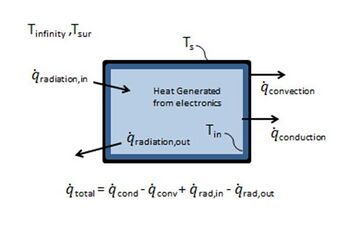
The Heat Transfer Goals are to finalize an insulation thickness for the cube that will keep the electronics at their operating temperature in a worse case scenario.
Preliminary EES Solution
- Required Specifications:
- Minimum Inside Cube Temperature of -15°F
- Altitude Dependent Values
- Assumptions:
- Carbon Fiber Structure Negligible
- DOW Utilityfit Insulation
- Generated Heat is removed by convection to the surroundings and radiation by the box
- Altitude of 80,000ft
- Solution:
- Insulation Thickness
- Total Power Loss
Finalized EES Solution
- The finalized solution adds radiative heat transfer as well as validates the prior exclusion of carbon fiber convective heat transfer in the code.
- Required Specifications:
- Minimum internal temperature at 0 °C
- Must maintain operational temperature TBD of transmitter hardware
- VAST data suggests minimum external temperature of -50 °C
- Minimum internal temperature at 0 °C
- Assumptions:
- DOW TUFF-R Insulation
- Generated Heat is removed by convection to the surroundings and radiation by the box
- Altitude of 80,000ft
- Solution:
- Insulation Thickness
- Total Power Loss
- Carbon Fiber Wall Convective Heat Transfer 0.056% difference
- Negligible due to wall thickness
Electrical Engineering
Electrical device selection is based on a worst case scenario model. The component requirements are as follows:
- Transmitter Requirements:
- 420-450 MHz
- Transmit minimum of 53 miles Line of Sight (LOS)
- For 80,000 feet altitude and 60 mile horizontal distance
- Board Requirements:
- Type of oscillator
- Silicon or Crystal
- High clock speed
- Type of oscillator
Flight Elements
Initial Flight Elements:
Transmitter Options:
| Transmitter 1 | Transmitter 2 |
|---|---|
Specifications
|
Specifcations
|
Board Options:
| Circuit Board | Specification |
|---|---|
Board 1
| |
Board 2
into the circuit (IC6/7 socket) |
Crystal Oscillator Selection:
Specifications:
- SG-8002JF-PCC (Digikey)
- 1 MHz-125 MHz
- Can be used with Spartan 3E TQ144 and CP132
- 3.3 V (max)
- 28 mA (max)
- -20C ~ +70C
- 7.1mm X 4.6mm X 1.5mm
Interim Flight Elements
Other internal flight elements were added to allow for proof of concept design to progress to a future cubesat design.
- CANSAT Kit Rev 2
- Pressure sensor
- Temperature sensor (not included)
- TMP37 Analog Devices
- One additional peripheral port - use of which is TBD
- Transmitter
- Meets AX.25 protocol
- Transmits at 433.92 MHz
- 5 g
- Power
- 9 V provides 5 hours of operation
- Up to 5 V transmit power
- Arduino compatible microcontroller
Ground Element
- Yagi antenna
- CANSAT Receiver
- Directional
Antennas
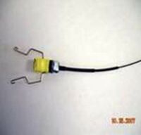
- Flight Antenna (Transmitting)
- 433 MHz quarter-wave dipole
- 17.3 cm length
- 433 MHz quarter-wave dipole
Wind Measurements
- GPS
- VAST system
- Doppler shift
- Use communications system to accurately measure doppler shift
- Use doppler shift to calculate satellite LOS speed
- Third method: external sensor
- Currently researching
Project Development
Mechanical Engineering
Cube Design
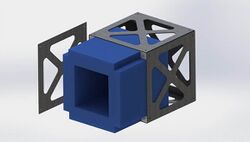
- SolidWorks Cube Model:
- Following CubeSat standard
- 10 x 10 x 10 cm, known as 1U
- Carbon Fiber Panels with Pumpkin CubeSat inspired cutouts
- Cutouts to adhere to hardware requirements
- Threaded Aluminum blocks for cube panel connections
- Milled Insulation to hold desired electronic operating temperature
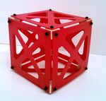
- Current Cube Structure Prototype:
A rapid prototyping machine was used to construct the initial prototype and basal wood cubes stood in place of the aluminum blocks. The insulation was not included.
- Structure uses six 0.96 x 0.96 cm carbon fiber squares
- 4 mm difference accounts for two 2 mm thick carbon fiber panels
- May need to account for screw heads by countersinking or further reducing panel dimensions
Manufacturing
- Tooling Plate:
The Tooling Plate is used for cutting out the carbon fiber panels. The tooling plate is mounted in our Haas CNC mill, the mill is zeroed to the tooling plate using reamed hole in top left corner. Carbon fiber blanks are mounted to the tooling plate and cut out using the mill.
- Cube Corners:
The Cube Corners are threaded to join all eight corners of the cube, made using SHARP manual mill.
Electrical Engineering
Link Budget Assumptions
| Best Case | Worst Case | Both Case |
|---|---|---|
|
|
|
Link Budget Results
- Free space loss: -112.17 dB
- EIRP:
- Best: 27.99 dBm
- Worst: 26.99 dBm
- Receiving antenna effective aperture:
- Best: 0.1911 m^2
- Worst: 0.07611 m^2
- Received power:
- Best: -77.18 dBm/-107.18 dBw
- Worst: -88.18 dBm/-118.18 dBw
Selected Transceiver
BHX2-433-5-SMA
- Radiometrix product
- Frequency: 433 MHz
- Transmit power: 500 mW
- Receiver sensitivity: -118 dBm
Antennas
Transmitting antenna
- 17.3 cm quarter-wave dipole antenna
Ground station/Receiving antenna
- 430 MHz yagi antenna
Preliminary Compliance Matrix
Mechanical
| Design Parameter | Requirement | Requirement Source | Design/Analysis Method | Calculated Values |
|---|---|---|---|---|
|
Mass |
Less than 2.7 kg |
FAA |
Solidworks 3D Modeling/Prototype |
0.185 kg - Current Prototype Mass (sans electronics) |
|
Thermal |
Internal Temp. 0°C-10°C |
Electronics Data Sheet |
EES Heat Transfer Model/Cold Chamber Testing |
0°C - EES Heat Transfer Model TBD - Cold Chamber Testing |
|
Dimensions |
1U - 10x10x10cm |
Cal Poly CubeSat Standard |
Solidworks 3D Modeling/Prototype |
Solidworks - 10x10x10cm
Prototype - 10x10x10cm |
Electrical
| Design Parameter | Requirement | Requirement Source | Current Design |
|---|---|---|---|
|
Transmit Antenna |
Linearly polarized, low gain |
Project Description |
Dipole/Monopole |
|
Receive Antenna |
Directional |
Project Description |
Yagi |
|
Data Acquisition |
2 Methods of Wind Speed Measurement |
Project Description |
GPS (VAST balloon), Doppler |
|
Transmission Frequency |
220-225 MHz 420-450 MHz |
FCC frequency allocation |
433.92 MHz |
|
Dimensions |
<1000 cm^3 |
Cal Poly CubeSat Requirements |
355 cm^3 |
Testing
| Structural | Communications |
|---|---|
|
|
Cold Chamber Test
Purpose: To obtain a relative range for the temperature drop inside & outside of the cube, for verification that the insulation system can maintain an electrical operating temperature between 0°C and 10°C.
Results: Graph the Temperature Drops vs. Time
- Outside of cube to Inside of cube
- Inside of cube @ start and end of test
- Chamber @ start and end of test
Cold Chamber Tests
| Temperature Validation Test | Decreasing Temperature Test (Idealized Flight) 1hr 30min | Constant Temperature Test (Worst Case Scenario) 30min | Increasing Temperature Test (Extended Landing) 1hr |
|---|---|---|---|
|
|
|
|
Results
- Temperature Validation Test:
- Completed Feb. 13th & Feb. 14th
Cold Chamber Decreasing Temperature Range
- 15°C to -58°C
- Minimum Temperature reached within 1hr
Cube Design Analysis Steady State Heat Transfer Code
- Includes Heat generation
- 9 Volt Batteries
- Handwarmers
Insulation Top Closure
- Air tight
Drop Test
Purpose: To verify that the external structure can withstand landing impact stresses and analyze design problems from fracture points.
- 1.5m Drop
- Kibbie Dome Parachute Drop
Results: Visual Assessment (VAST) Graph - Accelerometer Data of Impact (Tensegrity Group)
Antenna Chamber Test
Antenna chamber at Gonzaga University, 3 meters in length, will be used to conduct the tests on both transceivers.
- 3D radiation pattern
- Verify link budget
- Transmit power
- Receiver sensitivity
- EIRP
Will perform the radiation pattern, transmit power, receiver sensitivity, and EIRP test at room temperature then again with the transceivers cooled to 10°C.
Project Risks
- Thermal overheating or freezing of electronics
- Limited cold chamber testing time
- Further reducing structure size to compensate for screw heads and wall thickness to meet CubeSat standard limits internal space for communications system
- Cube fabrication may delay drop testing
- Spring launch dependent on weather
- Time to acquire components - shipping, back order
- System power
- Transmission distance
Project Timeline
November
- Finalize communications hardware
December
- Order most components
- Verify communication link
- Finalize structure
- December 6 Snapshot 2
- December 20 complete prototype
January
- January 23 Begin structure testing
February
- February 10 Complete all testing
- Start compiling paper
March
- Mid-March 2014 flight date
- Evaluate for areas of improvement
April
- April 25 Finalize paper
May
- May 2, 2014 Engineering Expo
Pantheon Team
| Team Members | Biographies |
|---|---|
|
My name is Aaron Kitchen. I am originally from Seattle, Washington. I am pursuing a degree in Mechanical Engineering with a minor in material science and writing. My experience in 3D modeling allowed me to receive two summer internships at The Boeing Company, where I worked as a manufacturing engineer for the Wind Tunnel and Flight Test programs. In my spare time I enjoy writing and baking. I look forward to returning to work for Boeing after I graduate in May 2014. | |
|
My name is Philip George Petersen. I am from Idaho Falls, Idaho and love all outside activities, mountain biking in particular. I thought this was what I was going to do with my Mechanical Engineering Degree. I have also studied German since high school and just finished my minor last semester. These two passions culminated in an internship with NICOLAI bikes in Lübbrechsten, Germany. I have found there and my other internship at Idaho National Laboratory (INL) that I love new challenges involving cutting edge technology, I saw both of these in this JPL project. I am excited for what challenges this project will pose and hopefully we will deliver a satisfying result. | |
|
My name is Jessica Slater. I am from Lind, Washington. I am majoring in Electrical Engineering. For the past four summers I have interned with the U.S. Government in Washington D.C. which allowed for experience in testing and research. Outside of school I enjoy read and cooking. | |
|
My name is Stephen Wayne. I am originally from Idaho Falls, Idaho. I am pursuing a degree in Electrical Engineering with a minor in business, and expect to graduate in May, 2015. I have interned at Schweitzer Engineering Laboratories in Reliability Engineering, and will be returning to NASA’s Jet Propulsion Laboratory in Radio Science Engineering for Summer 2014. I am interested in electromagnetics, robotics, and emerging technologies. | |
|
Rhys grew up in Idaho Falls and graduated from Hillcrest High School in 2009. He shared his father’s interest in electronics and computing which lead to his undergraduate studies at the University of Idaho. Mr. Perry will acquire his B.S. in Computer Engineering in December of 2013. In his free time, Rhys enjoys mountain biking, video games, and collecting LEGO sets. |
Presentations
Old_Design_Review_Presentation.pdf
