Solar Backup Power Generation
| team picture | |
| Sponsor | UI Facilities |
| Team Name | SBPG |
| Duration | Fall 2019 - Spring 2020 |
| Faculty Adviser | Dr Herbert Hess, Dr Feng Li |
| Mentor | Dr Herbert Hess |
| Client | Marc Compton |
| Team Members |
|
The project goal is to perform a site assessment to identify the optimal location for a solar panel array. Once an optimal location has been identified, we are to submit a completed design including component selection, one-line diagrams, and any necessary schematics and renders. Additionally we will create an economic analysis comparing the cost of the proposed array vs. a diesel generator.
Problem Definition[edit | edit source]
Assist the University of Idaho in the planning of a Solar Panel array to power two wells to ensure reliable water delivery. To perform this the following tasks will be performed:
- Investigate the three locations and select one to be designed
- Design the selected PV array including a solar site assessment, module selection, inverters, support structure, relays, meters, etc.
- Conduct an economic analysis of the system
Background[edit | edit source]
The university operates multiple wells to support the domestic water needs of campus. Backup power generation is needed for two wells in case a disaster occurs and the power grid goes down. Traditionally, diesel generators would be used, but University is seeking a solar PV alternative that can be tied into the campus microgrid. Based on billing data for the wells, we have calculated that the well pumps require approximately 1 MW of power.
Deliverables[edit | edit source]
Location Assessment[edit | edit source]
Specific Site Analysis Data Points[edit | edit source]
The following Site Analysis Data Points were analyzed:
- Obvious obstructions to sunlight/energy production
- Electrical Grid connection points
- Whether connecting to the microgrid makes sense
- Physical area available (standard commercial panels will require approximately 65,000 square feet to meet our generation goal of 1 MW)
- Construction requirements
- Panel Type and details including a cost analysis
- Foundational requirements (Panel framing)
- Physical location angle considerations
- Physical distance to the wells
- For sheep farm: Will the panels provide shade for the sheep? Will they impede on grazing area? Will the panels need to be fenced off?
- Snow Impact
Design Requirements[edit | edit source]
Component Selection Requirements[edit | edit source]
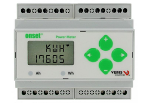
- Our choice for metering the wells is the SEL 735 meter (our client Marc Compton recommended the 735) which is an AC meter. We set up a panel on the roof of the steam plant, and since it doesn't have an inverter we need a DC meter which is shown in the picture.
- Inverters
- Protection as discussed with the microgrid team, or with Avista depending on if we connect to microgrid or main grid
- Energy storage
- Solar Panels
One-Line Diagram Requirements[edit | edit source]
Depending on the selected location, it may make sense to create Thevenin Equivalent Circuits, or a full one-line diagram of the system. We will be working closely with our client and the Microgrid Expansion team to ensure that all necessary circuit equivalencies are created.
Schematics and Renders[edit | edit source]
Schematics and 3-D renders of each project component may be created to visually demonstrate the design concept.
Economic Analysis Requirements[edit | edit source]
The economic analysis shall be a complete analysis which covers the entire life of the solar array. A cost/benefit analysis shall be conducted to compare the solar array with a typical generator cost for the load size of the wells. All reasonable economic aspects shall be analyzed and used in the comparison.
Site Assessment[edit | edit source]
Three sites were selected for analysis: The University of Idaho's Sheep farm, the Kibbie Dome, and Parking Lot #57.
Sheep Farm[edit | edit source]
Physical Location[edit | edit source]
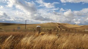
The sheep farm is very close to the wells themselves, but very far from the campus microgrid. The sheep farm also has the largest available area out of all prospective locations. The location being isolated from the microgrid means that we would need to create a new sub-micro grid which comprises of the wells and sheep farm buildings. This adds an extra layer of complexity to the project. This layer of complexity will be further compounded in the future. Ultimately, the goal will be to connect all campus buildings to the microgrid. Absorbing one microgrid into another is much more complex than simply expanding a single microgrid. The location is also located behind a large hill behind Winco, which will minimize the publicity of the array at this location.
Component Considerations[edit | edit source]
The sheep farm can use a standard frame which will very simply elevate the panels off the ground and allow the panels to be faced at a static angle. The panels used at this location would be standard commercial panels.
Other Considerations[edit | edit source]
The panels can provide shade and shelter for the sheep, and the sheep in turn reduce maintenance costs by eating the grass under the panels.
Kibbie Dome[edit | edit source]
Physical Location[edit | edit source]
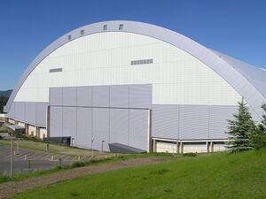
The Kibbie Dome is farther from the wells than the Sheep Farm, but much closer to the campus mircogrid. The Kibbie Dome has a roof surface area of approximately 98,968 square feet. The Kibbie Dome roof has a semi-circular cylindrical shape arcing in the North/South direction.
Component Considerations[edit | edit source]
The Kibbie Dome has a metallic frame structure with a thin sheet covering over the frame to create the roof. For our design, this structure means that using standard commercial panels and frames would not be possible. For the Kibbie Dome, a thin film panel would be required. Thin film solar panels have a typical trade-off of being either half as efficient while maintaining a similar cost to commercial panels, or being as efficient as commercial panels with almost twice the cost.
Other Considerations[edit | edit source]
Due to the shape of the Kibbie Dome and Moscow's latitude, placing solar panels only on the South facing side makes sense. Even then, only a small portion of the Kibbie Dome's south facing side would be at the ideal angle for generation. Additionally, due to cost constraints the Kibbie Dome would likely use thin-film solar panels which are only half as efficient as typical commercial panels. This means that the initial estimation of 65,000 square feet is doubled to 130,000 square feet for thin film solar panels. Recall that the Kibbie Dome roof only has 98,968 square feet, meaning that there is not enough physical area on the Kibbie Dome to meet the generation goal of 1 MW. Additionally, since only a small portion of the Kibbie Dome would be at the ideal angle, placing panels on the Kibbie Dome roof would only provide a small fraction of the generation requirements, and the project would require significant supplementation in power generation. The Kibbie Dome has a lot of good publicity potential since it is already a campus icon. The Kibbie Dome would have the highest maintenance costs due to the extra training and safety resources required to access the roof.
Parking Lot[edit | edit source]
Physical Location[edit | edit source]
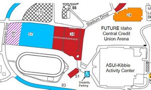
Parking Lot #57 is farther from the Wells than the Sheep farm, but much closer to the campus microgrid. The parking lot has an area of approximately 169,274 square feet.
Component Considerations[edit | edit source]
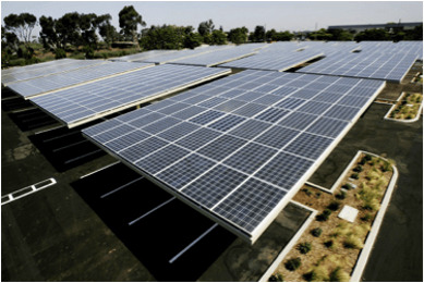
The design for the parking lot would consist of panels on top of a covered parking space structure. The panels used would be standard commercial panels.
Other Considerations[edit | edit source]
The parking lot would provide the greatest benefit to students by providing cars with some protection from the elements. Additionally the parking lot has a good publicity potential since the parking lot is used frequently by Alumni visiting for football games.
Location Summary[edit | edit source]
| Sheep Farm | Kibbie Dome | Lot #57 |
|---|---|---|
| Most available space | Unable to meet generation requirements with available space | Plentiful space |
| Easiest installation | High maintenance cost | Additional benefits beyond power generation |
| Farthest from microgrid | Easy connection to microgrid | Easy connection to microgrid |
| Almost no public visibility | Campus Icon | Good public visibility |
Final Site Decision[edit | edit source]
After discussion with our client in the design review, it was determined that the parking lot will be the location for the array. The design for this location will be a solar carport array.
Schedule[edit | edit source]
The following are major Project Milestones:
- 10/15/2019: Snapshot 1
- 11/20/2019: Location Assessment Due
- 11/21/2019: Design Review
- 12/06/2019: Snapshot 2
- 02/24/2020: Component Specification Due
- 02/25/2020: Engineering Release Review
- 03/06/2020: Snapshot 3
- 03/28/2020: Economic Analysis
- 05/01/2020: Design Expo
- 05/08/2020: Semester 2 Final Deliverables
Solar Carport Specifications[edit | edit source]
Description[edit | edit source]
Solar Carports consist of a standard roofed carport style design with solar panels mounted on top.
Components[edit | edit source]
Panels[edit | edit source]
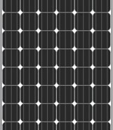
There are three main type of panels on market: Monocrystalline, Polycrystalline, and Thin-Film (or Amorphous) panels. After a comparison on price, efficiency, and payback period, it was determined that thin film is too expensive with low efficiency. Polycrystalline is a little bit cheaper, but it has lower efficiency and longer pay-back period compared to Monocrystalline. In conclusion, we recommend Monocrystalline as the panel type.
Frame[edit | edit source]
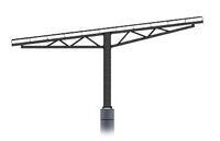
There are three main types of frame on market: T type, Y type, and L type. After the comparison on size (how many panels one frame can hold), price (L frame is most expensive), angle the frame can adjust to, efficiency, and the snow accumulation effect, we finally recommend T type of frame as the carport frame since it's cheaper than L frame and has little snow accumulation on top of the panel compared to the Y frame.
Source Model[edit | edit source]
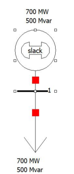
Our team is cooperating with Microgrid Expansion team to improve school backup power plan. Our new source and the load of the wells will eventually be connected to the campus microgrid. In an effort to assist the Microgrid team's goals, our team has provided the Microgrid team with a source and load model in Powerworld. This source and load can be used and modified by the Microgrid team to run in their Powerworld simulations to view the behavior of the campus power flow in the event of an Avista outage.
3D Model[edit | edit source]
Our team has design the 3D model for solar carport.
Project Learning[edit | edit source]
Throughout the course of the project our team has learned a great deal about many of the aspects related to the design and implementation of solar arrays, carports, and microgrids.
Wells Load[edit | edit source]
Since the main goal of our project is to supply power to two wells, it is necessary to size our array to be able to meet the demand of the wells. Based on metering data for the wells, we found that if the wells both operate at the same time, they will draw approximately 850 kVA of power. Since the wells are metered at specific time intervals, and not continuously, there is a possibility that the metering data did not capture the true peak values for the wells. To compensate for this unknown, we decided that oversizing the array power to 1 MW would be appropriate.
It is important to note that since solar panels produce DC power, they are almost always sized in terms of Watts. However, once a power inverter is applied, the array will produce AC power. The power drawn will depend on the power factor of the load we supply. So, as a clarification, in this webpage and in other documentation we almost always refer to our array as a 1 MW array since that is the standard nomenclature. However, a more true representation of our array is a 1 MVA array, since it is capable of supplying both real and reactive power through the power inverters.
Frame Research[edit | edit source]
The following websites are various companies that offer different types of frames and some that offer frames with panels.
https://pascalsteel.com/project/solar-carport-idaho/ (This is a great website that offers solar carports.)
https://aten-global.com/products/solar-carport/ (This is an example of the "one-stop-shop" vendors.)
https://help.helioscope.com/article/39-carports-in-helioscope/ (Helioscope is a useful solar planning software.)
https://powerssolarframes.com/carport-intstallers.html (This website has specific values for T and L type frames.)
https://1stamerican.solar/new-page/ (An example of some solar carport systems.)
https://www.bajacarports.com/solar-carports/ (Offers T-type and L-type frames.)
https://www.symtechsolar.com/complete-solar-pv-systems/solar-carport-hercules/ (Offers lots of IKEA style build-it-yourself frames.)
https://www.enfsolar.com/pv/mounting-system/2?page=1 (A great sortable compendium of a variety of options.)
https://www.absoluterv.com/solar-carports-shade-covers/ (A steel frame manufacturer with a variety of options.)
https://sunmodo.com/carport/ (Offers a variety of framing options.)
Spokane Microgrid[edit | edit source]
The Spokane Microgrid team found that bidirectional solar panels worked well for their design for the microgrid of the city of Spokane. Due to our approximately similar physical location on the Earth, we decided these panels were worth looking into as well.
Solorado[edit | edit source]
The website solaradoenergy.com is a great resource for information on Colorado University's solar carport project.
EnergySage[edit | edit source]
The website energysage.com has great compare and contrast between popular solar panels. It allows the user to quickly compare features of different panels including factors such as rated power and efficiency.
Solar Electricity Handbook[edit | edit source]
The website solarelectricityhandbook.com has an ideal panel angle calculator which determines your latitude on the Earth and calculates ideal panel angles for that location. We used this site to determine the optimal angles for panels to be the following:
70 degrees from horizontal in the Winter
44 degrees from horizontal in the Spring and Fall
22 degrees from horizontal in the Summer
Angle-Efficiency Relationship[edit | edit source]
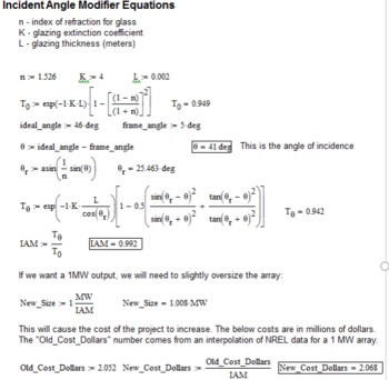
A big factor to the efficiency of solar panels is the Angle of Incidence (AOI). The AOI is the angle at which sunlight hits a solar panel. If a solar panel were pointed directly at the sun, the AOI would be 0°. Many of the frame designs can shift only between 0° and 15° from the horizontal, which means that our panels would never be at the ideal angle. Since our ideal angle on average is around 46°, a panel tilt of 5° would result in an AOI of 41°. Fortunately, there has been a good amount of research done on the AOI vs. panel efficiency relationship. We decided to use the De-Soto method which calculates an Incident Angle Modifier. This Modifier represents a the reduction in efficiency a panel will experience when it is not at the ideal angle. As shown in the math below, and AOI of 41° will result in an efficiency reduction of 0.8%. To compensate for this reduction in efficiency, we would oversize the array by 0.8% to 1.008 MW in order to reach a 1 MW output.
NREL's SAM[edit | edit source]
The National Renewable Energy Lab has created a program called System Advisory Model, or SAM for short. SAM is an incredible program for the modeling of various renewable energy systems. They allow you to select your location and automatically import local weather data to use in the simulation. You can select specific panels, inverters, connection types, tilt angle and direction, and a huge variety of other factors. We used SAM to model our expected system to view things like total power output which we use in our economic analysis.
Economic Analysis Estimation[edit | edit source]
Possible Incentives:
Business Energy Investment Tax Credit (ITC)https://programs.dsireusa.org/system/program/detail/658
This is an “investment tax credit” of 26%. This potentially means the University of Idaho would be eligible for a tax credit of 26% of the initial investment. An initial cost of $2.1 million minus a 26% tax credit would result in a new cost of $1.554 million, which is a significant reduction.
There are many incentives for reduction of property taxes. The University of Idaho is a “land grant” university, which we believe makes them exempt from property taxes.
Avista may offer rebates or incentives, but they do not specify on their website for the installation of solar panels. They do, however, require that you contact Avista prior to purchasing any equipment or services to be eligible, so it will be important for the University to contact them at the appropriate time.
At this time, we are awaiting more information on various incentives that the University will be able to take advantage of, so stay tuned!
Solar Revenue Estimate[edit | edit source]
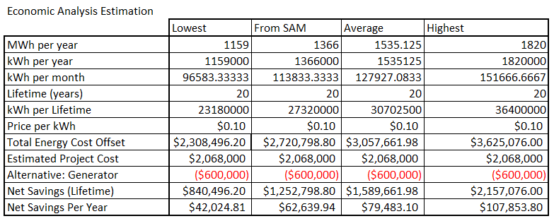
The following image shows our initial economic analysis data. The MWh per year information comes from the following paper:
Manoj Kumar, Nallapaneni & Samykano, M.. (2017). Techno-economic analysis of 1 MWp grid connected solar PV plant in Malaysia. International Journal of Ambient Energy. 40. 434 - 443. 10.1080/01430750.2017.1410226.
However, there is a column called "From SAM" which represents the MWh information that we got from our SAM modeling. This is likely the most accurate representation of our actual analysis, since the other numbers come from the paper above which is based in India. India has a more central latitude than we do, so their average would be expected to be slightly higher than ours. The Price per kWh number comes from the price that the University pays to operate the wells, which is the cost our project aims to offset. As we gather more research in regards to the Financial Incentives that the University is eligible for, we anticipate the Net Savings rows to increase.
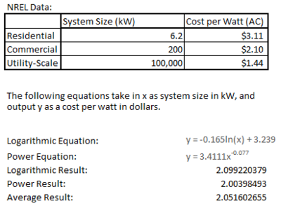
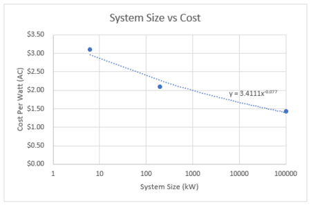
System Cost NREL Equations[edit | edit source]
Final Design[edit | edit source]
- We have done the site analysis for three locations: sheep farm, parking lot, and kibbie dorm, and decide to choose the parking lot as the final position to build our porject.
- We have choose to build the solar carport as our final project.
- We made all the research on panels, frames, companies, and angle-output efficiency and we can offer the best option to help companies build the solar carport.
- We choose the one-stop shop to build our project regarding to the project cost and matching of various hardware like inverters, meters, and relays.
- We have done our economic analysis and provided it for our clients.
- We have provided the microgrid team our source model and all the information they need to assist them in designing the entire grid connection.
- We have set up a solar panel on our university's steam plant roof to collect data for our project.
Validation[edit | edit source]
Design Validation[edit | edit source]
The validation of our design is in two parts: Client validation and Microgrid Expansion Team validation. In order for our project to be a success, the needs of all of our “customers” must be met.
Client Validation[edit | edit source]
Our primary client contact, Marc Compton, has provided us with much feedback over the course of the year. We worked with him to understand the needs of Facilities and how our project could meet those needs. We have strived to remain in close contact with him and others from Facilities to ensure that our project was always aligned with their needs in order to have short feedback loops if there were any problems. Based on feedback from Marc, our project overall has met the needs outlined by Facilities, and thus our project has been validated by our client.
Team Members[edit | edit source]
|
Name: Joseph Amodemo | |
|
Name: Salim Al Tubi
| |
|
Name: Emerson Butler
| |
|
Name: Boxiang Hou
| |
|
Name: Jiawen Yu |
Additional Documentation[edit | edit source]
Project Schedule
Meeting Agendas
To view in chronological order, click on the Name header.
Agenda Folder
Meeting Minutes
To view in chronological order, click on the Name header.
Minutes Folder
Presentations
Design Review
Engineering Release Review
Expo Presentation
Final Materials

