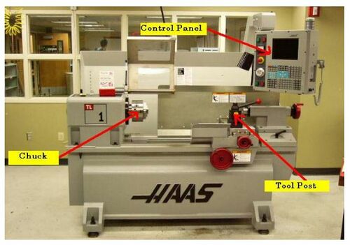
SolidCAM HAAS Lathe Startup Guide
Jump to navigation
Jump to search
SOLIDCAM HAAS LATHE STARTUP GUIDE[edit | edit source]
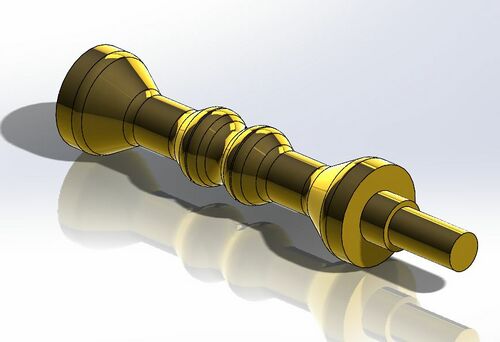
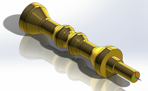
This tutorial details the process of producing a CAM code for the HAAS Lathe using SolidCAM by walking through the process for an example part.
Example Lathe Part SolidCAM Tutorial[edit | edit source]
- Design or import a part in SolidWorks.
- Save post processor files on the C: drive if they are not already present.
- Post processor files are located on the shared drive at: Z:\Engineering\SeniorDesign\- Group Folders\IEW\Machine Shop\SolidCAM Post Processor\Lathe HAAS
- Copy Postprocessor files to the local c drive at: C:\Users\Public\Documents\SolidCAM\SolidCAM2016\Gpptool
- Once completed, close both SolidCAM and SolidWorks and reopen to reinitialize.
- Open New Mill Turn part under the SolidCAM Part tab in SolidWorks
- File:SOLIDCAMLATHE2.JPGOpening a SolidCAM Turn Part
- Set up part (Suggested Settings)
- Fill in Part Data
- Under CNC-Machine Select: gTurn_Haas_2xUofIdaho
- Select: CoordSys
- Define an origin: click Select Face, then select Revolute Face.
- (The origin should be at the end of the part or a natural location to zero the tool. Z is in the direction of rotation)
- Click Green Checkmark
- (The remaining fields should auto fill)
- Create a Tool
- Double Click Tool List in design tree
- Select New Lathe Tool
- Select the tool you plan to use for the current operation.
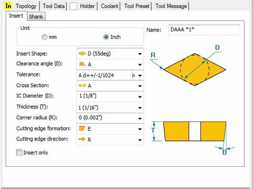
- Change the geometry of the Tool Insert as shown below.
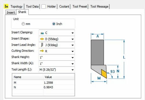
- Adjust the Shank Settings as shown below.
- Set Tool Parameters according to the material to be cut.
- (In this case carbide cutting 0.5” brass is selected)
- The HAAS lathe spindle's maximum speed is 1800 RPM.
- This website provides a feed and turning speed calculator: [1]
- Select the Mounting >> button in the upper right hand corner. In this menu use the Z+,Z-,X+,and X- buttons to orientate the tool such that it is positioned as it would be on the actual HAAS lathe's tool holder.
- The tools location in space is irrelevant. Pay attention to the axis orientation of the part.
- The X-Axis should point towards the operator when standing in front of the machine.
- When the tool is properly oriented, save and exit the mounting dialog.
- Make a Turning Operation
- Under Turning select the Turning Operation.
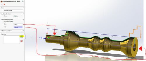
- Select the solid features to turn then click New Geometry in the Geometry Tab.
- Select the Start and End faces then the green checkmark to select a Chain.
- The Lathe will sweep the tool from the starting face to the ending face as is cuts the part.
- Care should be take to ensure that the tool, both the insert and holder, will not interfere with the part as it is swept along the part.
- Select the tool we previously defined.
- In the Levels menu, set the safety distance.
- 0.1” is acceptable.
- In the Technology menu, select the operation as desired.
- Technology refers to the machining styles / technique used. For example, if we were milling technology could refer to cutting a pocket using a spiral pattern or a level drilling followed by finishing sweeps.
- Under the Link menu, set the Lead In – Lead Out and the Approach and Retract settings.
- (Default settings are usually fine)
- Lean In and Lead Out refer to the x axis tool approach and retraction method.
- Approach and Retract refer to the z axis approach and retraction method of the tool.
