System for Next-Gen Wireless Devices
Jump to navigation
Jump to search
| Sponsor | |
| Duration: | Fall 2018 - Spring 2019 |
| Team Name | Next-G |
| Adviser | |
| Client | |
| Team Members: | |
Problem Definition[edit | edit source]
Background[edit | edit source]
-
With the widespread of wireless communication devices, there is an ever-growing demand for portable, low-cost, and easy to use devices that are capable of evaluating the electromagnetics performance of antennas or wireless devices/systems. Conventional measurement systems are very accurate but, in meantime, they are also bulky and expensive. This limits their use in field measurements, in classrooms, as well as in everyday life.
Deliverables[edit | edit source]
- 1: Design a simple system to test antenna.
- 2: Ensure the portability.
- 3: Ensure enough frequency.
Specifications[edit | edit source]
- Design an antenna characterization system for next-generation wireless devices to visualize the properties of an antenna system in an easy way and provide educational material to explain these properties to non-specialists.
- The device should test and show the impedance, total efficiency of antennas real time. At the same time, it should be portable and low-cost.
- We decide that the impedance and total efficiency to be our major measurement, if got more time, we may measure parameters as well. For the first three months, our major task is to assemble the prototype then test and improve it.
Design Considerations[edit | edit source]
Theory[edit | edit source]
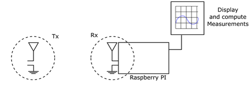
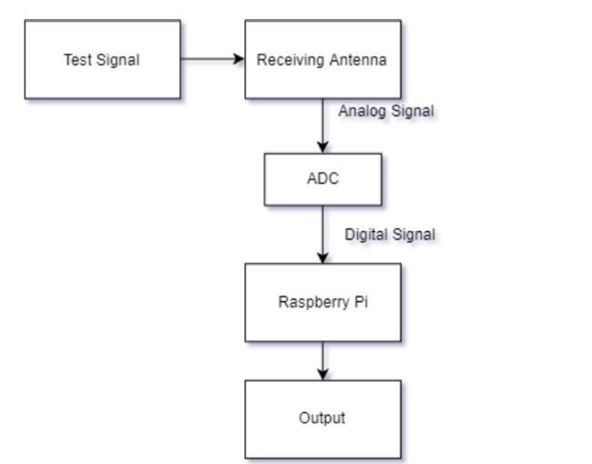
| The Diagram above illustrates how we will generate a signal with an antenna with known values, as seen on the left, and use our raspberry pi to measure and acquire the data from our unknown antenna for characterization. Characterization can either take place on the receiving raspberry pi itself or the computer can characterize the antenna. The computers main purpose is for visualization of our data. |
Current design[edit | edit source]
Project Learning[edit | edit source]
Final Design[edit | edit source]
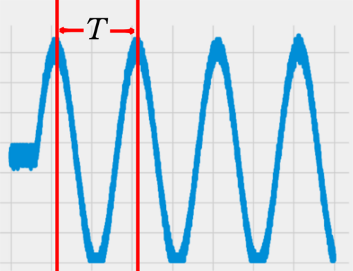
Simulation Signal Test[edit | edit source]
Experimental Progress[edit | edit source]
|
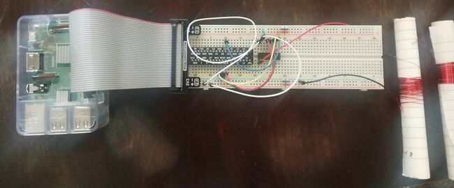
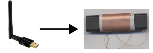
This is a very high demand for our system, so for testing purposes we are switching out the 2.4GHz antenna for a low frequency ferrite loop antenna. |
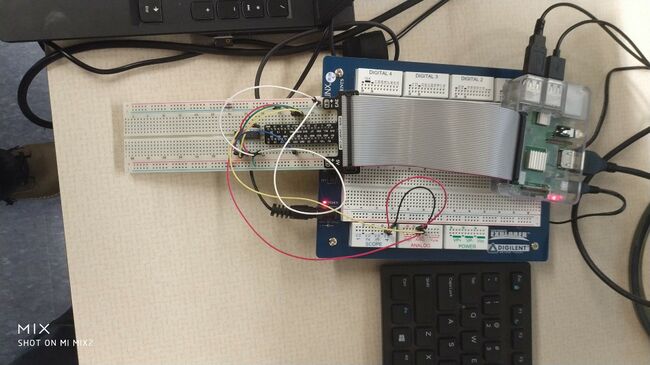
Total System Connection[edit | edit source]
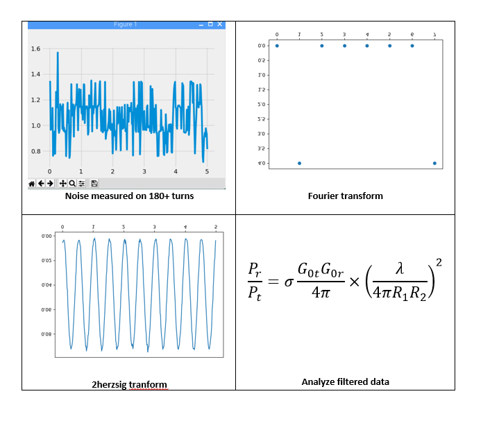
Data analysis[edit | edit source]
Future plan[edit | edit source]
- In the future we will use the data we have to solve for gain, power and distance.
- Then, We will also focus on the further analysis with additional hardware. If possible, we could also get a basic polar plot of antenna in dB linear scale.
- After all of this, we will try this system on a high frequency antenna and cancel the analysis we don not need.
Validation[edit | edit source]
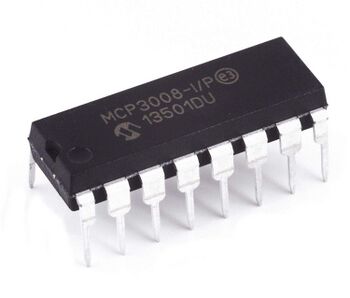
Task Name Start Date End Date Duration Status Assigned To Comments System for Next-Gen Wireless Devices 09/11/2018 04/26/2019 164d Completed N/A confirm the project content and meeting with client and instructor 09/11/2018 09/12/2018 2d Completed N/A Prepare for the project 09/13/2018 09/19/2018 5d Completed N/A Make sure the equipment with client 09/20/2018 09/24/2018 3d Completed N/A Change the equipment to raspberry pi 09/25/2018 11/05/2018 42d Completed N/A Delivery Window for Raspberry Pi 10/01/2018 10/15/2018 11d Completed N/A Design bypass of raspberry pi antenna for external antennas 10/01/2018 10/15/2018 11d Completed N/A Raspberry Pi readings to external code / Friis Equation development 10/01/2018 04/12/2019 132d Completed N/A Find ADC first and test the circuit 10/16/2018 11/27/2018 31d Completed N/A Buy ADC: MCP3008 and bread board 10/16/2018 10/31/2018 12d Completed N/A Connect the Raspberry pi and the ADC to get some data 11/01/2018 11/05/2018 3d Completed N/A Improve the circuit 11/07/2018 04/02/2019 146d Completed N/A Solder the wires to the SMA connector 01/10/2019 01/10/2019 1d Completed N/A Find the code and the software of Raspberry to plot the diagram 01/11/2019 01/18/2019 6d Completed N/A Install the software of the Real-time data dynamic graph 01/19/2019 02/01/2019 11d Completed N/A Figure out the problem of the dynamic 02/01/2019 03/08/2019 36d Completed N/A Input signal and output the virtual dynamic graph 02/08/2019 02/14/2019 5d Completed N/A Figure out the noise of the dynamic graph 02/26/2019 03/08/2019 10d Completed N/A Spring break 03/11/2019 03/15/2019 5d N/A N/A Find the problem that ADC is too slow to catch the antenna signal 03/19/2019 03/19/2019 1d Completed N/A Decide to perform Plan B 03/19/2019 03/20/2019 2d Completed N/A Make a DIY antenna 03/21/2019 03/26/2019 4d Completed N/A Test the antenna and find 100 turns is the best choice 03/26/2019 04/02/2019 6d Completed N/A Solve the code of plotting curve 04/02/2019 04/12/2019 9d Completed N/A Test the whole system with the new antenna and code 04/15/2019 04/23/2019 7d Completed N/A EXPO DAY 04/26/2019 04/26/2019 1d Completed N/A Team Information[edit | edit source]
Additional Documentation[edit | edit source]
Project Schedule
- Project Schedule
- Project Portfolio Links:
- System Diagrams
- Project Learning
- Manufacturing
- Balance Sheet
- Design goal
- 9.6-10.4Specifications and Constraints
- 9.6-10.4Meeting Minutes
- Experimental Design
- Analysis of Alternatives
