Virtual Fence IC Design
| Sponsors | Uidaho CNR and Design Magnitude |
| Team Name | Shock'em |
| Duration | AUG,2019~MAY,2020 |
| Faculty Adviser | |
| Client | |
| Team Members |
|
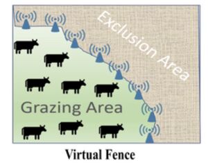
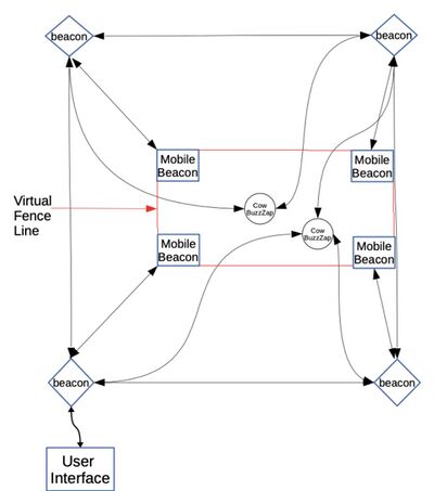
The goal of the project is to design a virtual fence system that keeps cattle in an enclosed area. The system consists of posts along the perimeter and low weight and power devices on the cattle that delivers high voltage stimulus if cattle are near the perimeter.
Problem Definition[edit | edit source]
Now the current limitations are
Background[edit | edit source]
We used to use a barbed wire fence as a border to restrict the movement of cow. But the barbed wire cost is very high and not easy to move, it may injure animals, And requires regular maintenance. Also the rancher cannot check the position and status of the cow at any time. He must go to the farm on his own to see if the cow is out of range.
Value Proposition[edit | edit source]
Current virtual fencing attempts rely on bulky, power- hungry, GPS-based systems with limited scalability for typical range livestock operations in Idaho and the West due to expense and connectivity requirements. This project aims to reduce costs and power requirements by locating cows using local beacons and administrating a shock or warning sound to the animal via a device in their ear tag.
Deliverables[edit | edit source]
Permanent Beacons[edit | edit source]
Mobile Beacons[edit | edit source]
User Interface
BuzzZap Device (Device on the cow)[edit | edit source]
Specifications[edit | edit source]
Nanotron Devices
Design Considerations[edit | edit source]
We are developing a simplified,low-cost approach to virtual fencing that leverages animal physiology and behavior, proximity beacons, and lightweight electronic nose clips to manage cattle distribution.
Trilateration[edit | edit source]
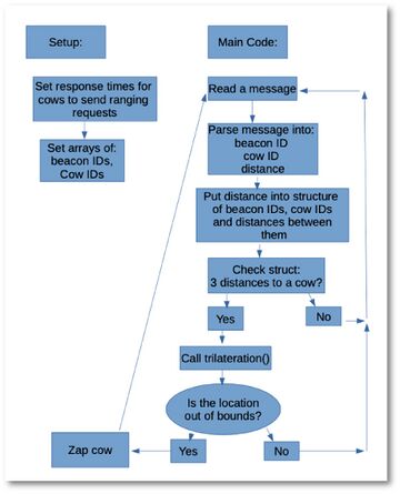
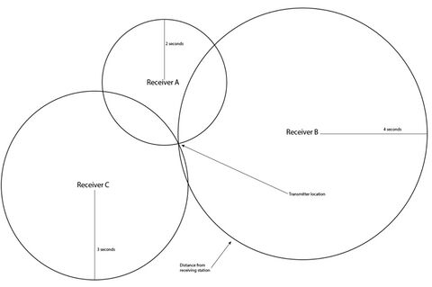
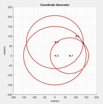
It's a method to determine the location of a movable vehicle or stationary point in space using multiple ranges between the point and multiple spatially-separated known locations.By measuring the distance between the unknown point and the three known points, and taking the three known points as the center of the circle and the distance from the unknown point as the radius, we draw the circle,the three circles intersect and produce only one intersection point, so we can know the coordinates of our unknown points.
The beacons can be put at any position,and we can get the location of these base beacons by GPS, add them into our code, and then the GPS data is no longer required in our project.
This method allows for error from:
Nanotron Program[edit | edit source]
PCB[edit | edit source]
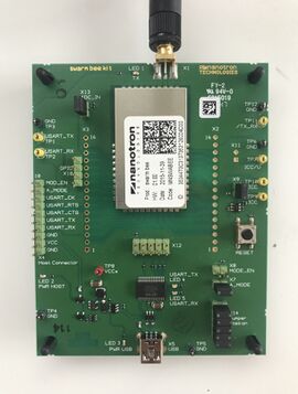
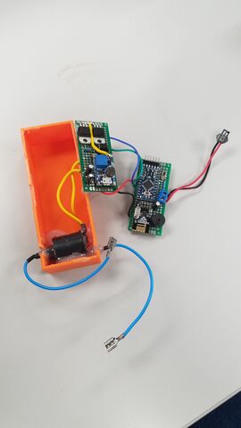
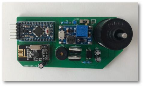
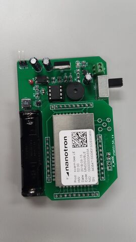
The shock circuit prototype shown, is designed to fit on the cow’s ear tag. The device has a Nanotron module incorporated. The device can send and receive signals via the Nanotron module and shock the cow or buzz the cow after receiving instructions from the permanent beacon devices.
Project Learning[edit | edit source]
Field Test[edit | edit source]
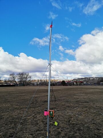
We need to do some field tests to check if our locating system is worked.
First Field Test[edit | edit source]
Second Field Test[edit | edit source]
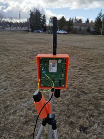
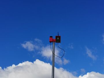
Design Evaluation[edit | edit source]
Physical Requirements[edit | edit source]
Steers are notorious for destroying anything that is on or near them. For this reason, the biggest concern is the durability of the device itself. The original device was intended to attach to a steer’s septum, that is the soft fleshy part just inside the nasal cavity. Several versions of the case were designed and printed with a 3D printer and tested by placing the devices on an animal while they were confined by a squeeze chute. The animals were released and monitored for up to a month. Testing showed that no matter what design was considered, the animals would rub the device on the ground or on a fence post to remove them forcefully. Some designs fell off as the plastic heated in the sun and deformed. The few devices that did remain often caused irritation within the nasal cavity or in the extreme circumstances, pierce the septum. Ear tags are already a commonly used product designed to remain attached to a steer at all times. Ear tags are small enough that most animals will not rub on them excessively. Because of this, and ear tag design is going to be used moving forward. A company in Australia specializes in producing double ear tags. These double ear tags have electrodes that can be placed on each hole as shown in FIG. 4 in the Concepts Considered section. However, the weight of the total device, including the casing itself, must weigh less than 50 grams. Due to current circumstances, a case has not yet been developed. The current circuit design has a weight of approximately 75 grams. Further development is required to reduce the size and weight of the ear tag device.
Electrical Requirements[edit | edit source]
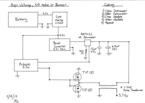
Testing steers on shock sensitivity using existing electric dog collars showed that steers react in a definite way, movement timed with applied stimulus, to voltages of 4 kilovolts when applied to the ear. Some steers that had grown accustomed to the test would often require 6 kilovolts. Various high voltage wave forms were tested including DC, pulsing, and AC. Frequency and shock duration were also tested. In the end, an affordable solution was found were steers would react with minimal power requirements. A large requirement was that the device must last four to six months on battery power. The circuit was designed to draw as little power as possible. The current model consumes a couple microamps when in standby mode and six hundred milliamps when actively outputting high voltage stimulus. Because it is unknown how often the animal may receive stimulus, a supplement power source is required. Solar power was added with a regulating chip to charge the battery and can do so at a rate of fifteen milliamps even in very low light conditions. The largest concern regarding the dFMEA is the battery. LiPo batteries do not like excessive heat, improper charging, excessive discharge, or physical damage. These events could lead to the battery catching on fire. To mitigate the risk, the LiPo battery has a built-in discharge circuit that disconnects power in the event of a short. Charging is handled by a dedicated IC specifically designed to charge LiPos from solar sources. The physical aspect means locating the battery away from a location where it is likely to get damaged. As a whole, the device should last several years and should be reused as the herd rotates.
Future Work[edit | edit source]
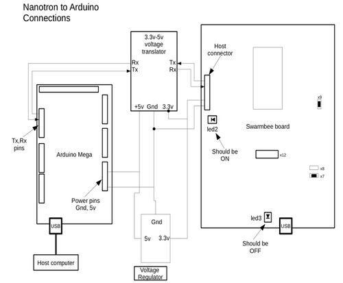
There has been a lot of work done on the project this year. The project has advanced significantly, and there is a working proof of concept design that can locate multiple “cows” and shock and buzz when needed. However, there is a lot more to be done on the project for it to be ready for the market. First, there needs to be more work done with the Nanotron devices in order to make them more accurate and reliable. There needs to be more research done in to how to set exact timing for the devices. There also needs to be more work put into determining how to extend the range of the devices beyond 500 meters. Additionally, more printed circuit boards need to be made. The permanent beacon devices need to have an Arduino shield built that connects the Nanotron module to the Arduino in a more compact and reliable format. The cow buzzap devices need to also be more compact and light-weight so they can fit on the cow’s ear tag. Finally, the devices for the mobile fence posts need to be made. Once these additional steps are taken, there will need to be rigorous testing on real animals. There may need to be adjustments to the frequency at which the devices communicate in order to make the system more practical for use in the real world. There could be another year or two at least of work to be done before the system is as reliable and efficient as it should be to be used on the market. As the advancements listed above are made, the overall cost of the system should reduce significantly. Work may be done to reduce the costs of the Nanotron devices either by contracting with the company, or designing a new device that can handle time-of-flight technology.
Team Members[edit | edit source]
|
Name: Xuyue Gu
|
Name: Ziqing Zhu
| ||
|
Name: Austin Grieve
|
Name: Lauren Smith
| ||
|
Name: Samantha Baran
|
Additional Documentation[edit | edit source]
Project Schedule
File:2019 Shock'em Project Schedule.pdf
File:2020 Shock'em Project Schedule.pdf
Meeting Minutes
File:2019 Shock'em 9-19 Meeting Minutes.pdf
File:2019 Shock'em 9-26 Meeting Minutes.pdf
File:2019 Shock'em 10-3 Meeting Minutes.pdf
File:2019 Shock'em 10-10 Meeting Minutes.pdf
File:2019 Shock'em 10-17 Meeting Minutes.pdf
File:2019 Shock'em 10-24 Meeting Minutes.pdf
File:2019 Shock'em 10-31 Meeting Minutes.pdf
File:2019 Shock'em 11-7 Meeting Minutes.pdf
File:2019 Shock'em 11-14 Meeting Minutes.pdf
File:2019 Shock'em 12-5 Meeting Minutes.pdf
File:2020 Shock'em 1-16 Meeting Minutes.pdf
File:2020 Shock'em 1-22 Meeting Minutes.pdf
File:2020 Shock'em 1-29 Meeting Minutes.pdf
File:2020 Shock'em 2-5 Meeting Minutes.pdf
File:2020 Shock'em 2-12 Meeting Minutes.pdf
Presentations
File:2019 Shock'em Snapshot.pdf
File:2019 Shock'em Presentation.pdf
File:2020 Shock'em Presentation.pdf
File:2020 Shock'em EXPOPresentation.pdf
File:2020 Shock'em EXPOposter.pdf
Client Interview
