Bolster Rivet Press
| Bolster Rivet Press. | |
| Sponsors | |
| Team Name | VandalBucks |
| Duration | Fall 2013 - Spring 2014 |
| Faculty Advisers | Steven Beyerlein |
| Mentor | Rory Lilly |
| Team Members | |
The goal of this project is to create a test fixture and associated calibration methods to measure the required force to optimally compress and seat rivets in the production of knives. Also to Provide assistance to both designers and machine operators that improves the quality and consistency across a spectrum of knife families.
Problem Statement
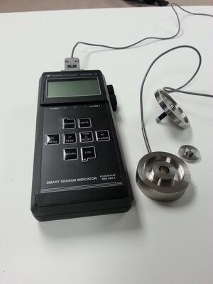
Design a force calibration tool comprised of a load cell and digital display to aid in the calibration of rivet presses in operation
Background Information
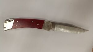
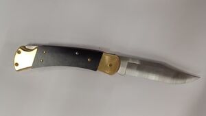
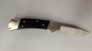
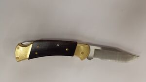
Buck Knives currently produces several common knife models that are held together with bolster rivets. Last year, Buck Knives supported a senior design project where the team was tasked with creating a machine that inserts pins into three locations in the knife. This year we started out re-creating a bolster rivet press to press these pins to hold the knife together. Initially Buck Knives thought they wanted there old bolster rivet press for there 110 and 112 models replaced. Later they realized that having precise force measurements and a calibration device would be more beneficial. The calibration device would not be for the one press but all that they currently are using for manufacturing knives.
Knife Models
Design Specifications
- Device is of universal design
- Fits all presses in operation (required)
- Compatible with a standard laptop (desired)
- Produces accurate readings
- Measure force (required)
- Measure displacement (desired)
- Control load w/manual actuation
- Readouts
- Built in display or
- Displays on laptop (desired)
Design
Parts
| Picture | Part | Description |
|---|---|---|
| Bottom Plate |
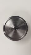
This stainless steel plate serves two purposes. The first is to align the load cell perfectly with the hydraulic press so that all the force is in the axial direction and no moments are produce to insure quality of the readings. The second purpose is to protect the load cell’s surface. The idea is to let the plate get scratched and marked up allowing the load cell to last longer. | |
| Top Plate |
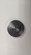
This Stainless steel plate is designed to protect the load cell allowing it to last longer. The hydraulic presses have anvils on the ends that have a waffled pattern. Without the protective plate this pattern can were away the surface of the load cell, destroying it over time. | |
| Silicon Case |
This is a silicon case fabricated to fit tightly over the display device. In the event the display device is dropped the silicon case will help absorb a lot of the energy from the impact lessening the chance for the device to break. | |
| Display and logging device |
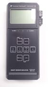
This is a purchased part from Transducer Techniques. It displays the values from the load cell and has the option to record the numbers for data acquisition purposes. | |
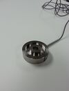
| Load Transducer |
This load cell works in tandem with the display device to produce accurate force reading. This load cell is accurate to plus or minus nine pounds. This part was also purchased from Transducer Techniques. |
Testing
SATEC Testing
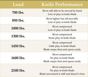
Before starting testing we determined there were four critical conditions that had to be met. The pins had to be press hard enough to hold the knife together well and to keep the knife blade stable but not pressed to the point that it will hinder the knife's ability to open and close. Also the knife could not be physically damaged by the pressing process. Though testing with the satec machine we have discovered the optimal force to be used one each rivet is in the range of 2000-2200lbf. In this optimal range all four conditions and were all satisfied.
Testing Apparatus
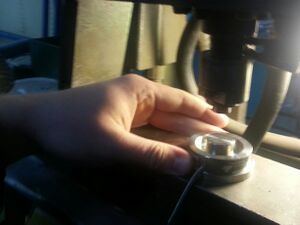
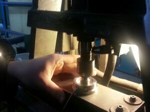
This testing apparatus was designed and built to mimic the hydraulic presses being used by Buck Knives on their shop floor. This device uses the same anvils that all the presses at Buck Knives use. Using this device in the SATEC machine, data was produced and collected to determine the optimal force it takes to properly seat a rivet.
Finial Testing At Buck
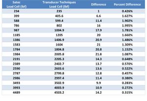
Charts
Click Charts for Larger View
Meet The Team
Team VandalBuck
Sponsor
This Project is supported by
Buck Knives
660 S. Lochsa Street
Post Falls, ID 83854-5200
| Picture | Member | Bio |
|---|---|---|
| Mitch Miller |
Hello, I am Mitch Miller. I am a senior in mechanical engineering at the University of Idaho. I have attended this great school during my entire college career. During this time I have been part of many great projects including this one. Currently I am set to graduate May of 2014. I fill my free time with various activities including swimming, working out, and biking. | |
| Ryan Borth |
HI, I am Ryan Borth, I am currently a senior in mechanical engineering at the University of Idaho. I expect to graduate in May of 2014 with my bachelors of science. Throughout my education I have had many opportunities to be involved in some interesting projects. These currently include redesigning a bolster rivet press for Buck Knives, being a part of an international Catia project, and doing research for a professor. | |
| Luke Nelson |
Luke is currently a senior in Mechanical Engineering from Walla Walla, Washington. The past few years he has been a member of the American Society of Mechanical Engineers and the University of Idaho Industrial Assessment Center. His academic interests include machine design, solid modeling and simulation, and thermodynamics. Following graduation Luke plans to work in industry, preferably for a manufacturing company. When not working on school related activities Luke enjoys spending time in the outdoors, backpacking, hunting, fishing, skiing, and many other activites. | |
| David Erikson |
HI, my name is David Erickson, I am currently a senior in mechanical engineering at the University of Idaho. I will graduate in May of 2014 with my bachelors of science. I am currently working on optimizing the forces used in assembling knives for Buck as well as presenting them with a portable load cell calibration device. My interests include skiing, camping, hunting, and working around engines. I hope to find a job in an area of my interest once I graduate. |
Design Documents
Test Apparatus: Drawing Package
File:2014 VandalBucks base drawing.pdf
File:2014 VandalBucks block drawing.pdf
File:2014 VandalBucks top drawing.pdf
Top and Bottom Plates: Drawing Package
File:2014 VandalBucks Load Cell Bottom.pdf
File:2014 VandalBucks Load Cell Top.pdf
References
Reports and Presentations
File:2014 VandalBucks Presentation.pdf
File:2014 VandalBucks Design Review 2.pdf
File:2014 VandalBucks Future Tasks.pdf
File:2014 VandalBucks Midsemester Report.pdf
File:2014 VandalBucks Progress Report.pdf
Meeting Minutes
File:2014 VandalBucks Meeting Minutes.pdf
Project Schedule
