Robotic Manufacturing Cell
| Work Cell | |
| Team Name | CyberCrew |
| Sponsors | |
| Team Members |
|
| Duration | Summer 2018 - Fall 2018 |
| Faculty Adviser | Dr. Steven Beyerlein |
| Mentor |
|
| Client |
|
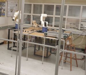
The Integration of two robotic entities into a miniature assembly line, in order to make a product involving operations of barcode scanning, part manipulation, fixture design, and supervisory control.
Problem Definition[edit | edit source]
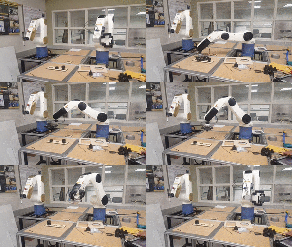
In past projects, teams have not been able to integrate the two robots into one process. Our goal this year is to ensure this happens. New end effectors will be necessarily designed in order to assemble the products. The final process, put simply, will be to mechanically sort through various male and female pieces using a ramp. Once the two are separated into their respective destinations, the arm will grab the male pieces, scan them, and place each into their respective destination in the construction zone, then grab the female pieces and place them on top of the male ones. The other robot will then push the pieces together using the constructed end effector. Afterwards, a conveyor will distribute the pieces. This way, the two robots will be working together in one manufacturing process.
Background[edit | edit source]
2013-2014 In Spring 2013 The Boeing Company donated DENSO robotic arms to The University of Idaho College of Engineering. That fall Mechanical and Electrical Engineering students, as a part of Team Roboshow, were tasked to learn basic programming of the robotic arms and create a work-cell for the arms. Their work-cell incorporated multiple safety features as well as a clear poly-carbonate enclosure for public demonstration. The team was able to successfully program the robot to use a dry-erase marker to create logos and patterns on a white board.
2014-2015 The following year another design team, known as Team Vandalbot, was formed to design a manufacturing process which could assemble various rivet and nut-plate assemblies in order to automate a repetitive task currently done by factory workers. The team was able to demonstrate this process and provide documentation for future teams.
Summer-Fall 2016 During the Summer and Fall of 2016 Do All Robotics completely redesigned the robotic manufacturing cell. They made the cell larger which allowed for operators to have easier access to the robots for things like maintenance or changing end effectors. They also made the work cell fully modular allowing future teams to rearrange the cell for their specific needs. New pedestals for the robots were also designed because the originals were very unsteady. The team also performed stress analysis on the new pedestals to ensure they wouldn't break or fall over during operation. The team also programmed the robots to do tasks such as stack cups and write with a marker on a board. Finally the team also created a simple beginners manual that included all the basics needed to run the robot.
Summer-Fall 2017 The next year, the design team for the Robotic Arm Manufacturing Cell, Team CSRM, integrated a simple vision system involving a scanner, so that the arms could sort through two varied parts. These parts, a rectangle and a hexagon, were created by the team members, as well as the fixtures these parts were based in. Their process involved one of the robotic arms picking up pieces from a randomized mixture, then scanning the object to sort between the two. To pick the objects up, the robot used a pneumatic gripping mechanism.
Client Needs[edit | edit source]
Our client is Ankit Gupta, the professor for the industrial automation class. Working on this project could inspire future assignments for the class, as well as requests for perhaps even more progression for students to learn about these robotic arms. This will enable enhancements to improve the class. As the request for this specific project, we are tasked to integrate the two arms into one manufacturing process. Other requirements involve using the scanner to “see” which part is which: male or female. In order to perform this process, unique end effectors and fixtures will need to be designed, which will be available for future class use as well.
Deliverables[edit | edit source]
- Incorporate two robots in one manufacturing process
- Design and construct male and female parts
- Design and construct end effectors to assemble the parts
- Design and construct an incoming queue ramp
- Design and construct a fixture for the assembled part
- Use the scanner to sort through various pieces
- Design and construct a conveyor
- Integrate all 4 equipment to work together
Design Specifications/Constraints[edit | edit source]
| Device | Specification | Variable Limit |
| Robotic Arm | Fixture Mass | 5 Kg |
| Robotic Arm 1 | Gripper Pressure | .39 MPa |
| Robotic Arm 2 (Nr. 196-549) | Arm Maximum Coordinate length | 762 mm on x-axis |
| Ramp | Female Slide Angle | 40° |
| Ramp | Male Slide Angle | 62° |
| Conveyor | Maximum Belt Tension Force | 5 lbf for 0.139 HP Motor |
| Conveyor | Kinetic Friction Nylon-Dry Aluminum | μ=0.21 |
Project Learning[edit | edit source]
- Step 1: Load queue, establish connection with Arduino (Operator loads assembly parts into the ramp, checks Arduino Serial Monitor for connection)
- Step 2: Exit Cell (Operator departs manufacturing cell)
- Step 3: Start Program (Operator executes code)
- Step 4: Scan Males (The males are grabbed out of the ramp and scanned for color type with bar code scanner)
- Step 5: Move males to intermediate storage (Robot 1 (R1) will move males to intermediate storage as the base of assembly)
- Step 6: Scan Females (The females are grabbed out of the ramp and scanned for color type with bar code scanner)
- Step 7: Move females to intermediate storage (Robot 1 (R1) will move females to intermediate storage as the top of assembly)
- Step 8: Assembly (Robot 2 (R2) will push female part with designed "Finger" end effector, clamping the pieces to create assembly)
- Step 9: Moving Assemblies to Conveyor (Robot 1 will move each assembly to a specified location on the conveyor)
- Step 10: Turning on Conveyor (Robot 2 will move over the scanner to send a signal to the Arduino)
- Step 11: Distribution (Conveyor will turn on and move all of the assemblies to storage)
- Step 12: Product Storage (Final assemblies will be placed in a box once it is put together)
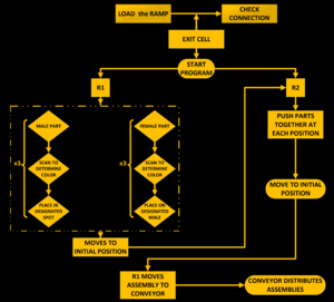
| Flow Chart | Description |
| Initially, before the program is started, an operator needs to both load the ramp queue with the male and female parts. Each will fall into its own lane. The operator also needs to ensure a connection is established with the Arduino. The operator then must leave the cell. The male parts are scanned and distributed to the assembly zone. Each color has a set location in the zone. Once the three males are in their destinations, Robot 1 will then do the same with the female parts, scanning to determine color, and placing each onto the respective male. Robot 1 stops in a specified location to clear the way for Robot 2 to push the assemblies together. A TCP/IP signal is sent from Robot 1 to Robot 2 to tell it to move. Once the parts are assembled, Robot 2 will send a signal to Robot 1 to pick up each assembly and place them onto the conveyor belt. When this process is completed, Robot 1 will return to the same position as before and send another signal to Robot 2 in order for it to move to the scanner, which will send a signal to the Arduino. When this signal is received, the motor will turn on, moving the conveyor belt and distributing the aseemblies. |
Design Solution[edit | edit source]
Proof of concept[edit | edit source]
| Primary Achieved Goal | Description | Methodology |
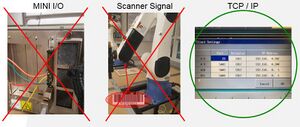
Initially we had three choices to implement the connection between the two robot arms.
|
System Architecture[edit | edit source]
| Solid Model | Description | Physical Model |
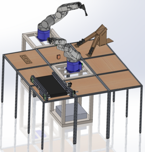
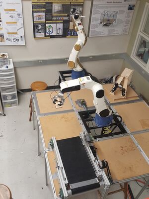
| The room layout has a diagonal equipment arrangement which allows Robot 1 to make a 180° rotation from the beginning of the process to the end. This arrangement seemed to be the most efficient way to assemble and deliver the part. |
Part Design[edit | edit source]
| Male and Female Parts |
|---|
| Final Design |
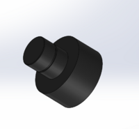
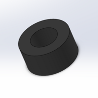
The manufacturing cell will operate with two unique types of parts: male and female. During the process, male parts will serve as a bottom base of the whole assembly and the female part will be placed onto the top of the male part, creating the final assembled product. There will be 3 assemblies with free different colors: Gold, Silver, and Black.
The Male part has:
- Design Software: 3D SolidWorks
- 2" height
- 2" outer diameter
- 1-0.001" inner diameter of rod (slip fit)
- 1" rod height
The Female part has:
- Design Software: 3D SolidWorks
- 1" height
- 2" outer diameter
- 1" inner diameter (slip fit)
- hollowed through
- Manufactured: Sindoh 3D Printer
- Material: 100% PLA (plastic)
Male part has a channel for the o-ring which serves the function of clamping the two parts together.
Ramp Design[edit | edit source]
| Solid Model | Description | Physical Model |
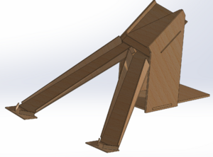
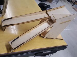
| The ramp is designed to sort the male and female parts. In the Robotic Manufacturing Cell the ramp is the first station to deliver the parts. The top base of the ramp is designed to have a 20° slope in the x-direction and a 45° slope in the z-direction, that way all female parts slide to the left side and all male pats slide to the right side because of the angled plate attached right above female side. This obstruction limits the access of the males to only the left side of the ramp for male parts and guides them straight to this side. In the physical picture , it can be observed that each end of the slide has a special end fixture designed exactly for the parts, and they are removable. The slope of each slide is different because of the different centroid of each part, which is calibrated to slide not very fast and not very slow, and to dump over the end fixtures of the ramp. |
Push Finger Design[edit | edit source]
| Solid Model | Description | Physical Model |
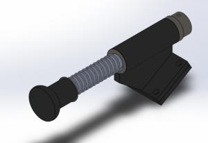
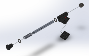
| Push finger designed for Robot 2, functioning by pushing the assembly together until it clamps.
The total length of the end effector is 7.5 inches and it is composed of:
|
Gripper Design[edit | edit source]
| Solid Model | Description | Physical Model |
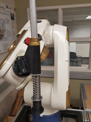
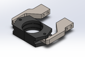
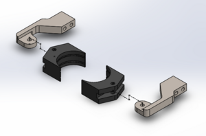
| The Gripper is used by Robot 1 to grab the parts of the assembly and put them in the desired places.
The material used for building this end effector is 100% PLA (plastic) for the claws, manufactured in a 3D printer. The Gripper arms are made from aluminum manufactured on the CNC Mill Machine. The claws were made from PLA material because it was necessary to maintain the flexibility to change the claws if it was decided a different shape of parts were required. The 3D printer makes this manufacturing process quick and easy. The parts have a 2 inch diameter, which was why we maintained the 2 inch diameter between the claws. |
Fixtures Design[edit | edit source]
| Solid Model | Description |
|
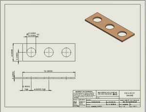
The figure represents the assembly storage. Robot 1 will grab the parts and place each in the spot designated, based on the bar code. Each part has a different color, and therefore a different barcode, so each part has its own location. In this station the assembly process takes place, requiring the function of both robot arms. The storage fixture has a capacity of 3 assemblies, as shown in the figure. The material is wood, and the manufacturing process utilized was the laser cutter. Hole dimensions are also shown as can be seen. |
Barcode Scanner[edit | edit source]
| Physical Model | Description | Technical Manual |
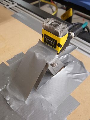
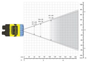
| The Barcode Scanner has one of the main functions in the manufacturing cell. It functions to scan, recognize the parts, and give relay a string to Robot 1. The scanner has resolution of 752 x 480 pixels. The other specifications you can find in the Reference Manual attached to the following link → Scanner Reference Manual, Scanner Quick Reference Manual |
Conveyor Design[edit | edit source]
| Solid Model | Description | Physical Model |
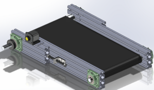
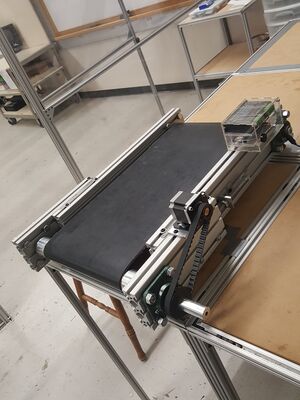
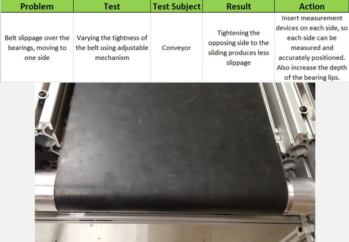
| For delivering the finished parts to the final destination, we built an automated conveyor belt. The conveyor frame is built from 8020 aluminum profiles of 6061 series alloy. The belt is made from rubber material on the top and the bottom (drive side of the belt) is made from a material close to that of Nylon. The friction coefficient obtained experimentally between two surfaces (Dry Aluminum and the Unknown Material) is 0.21, which is close to the friction factor of Dry Aluminum and Nylon.
The frame of the Conveyor consists of two parts. Part one is the Base Frame, which presents the longest base side of the frame. The second part of the frame is the adjustable part, designed specifically for tightening the belt. The belt also has a tightening mechanism which is shown in the pictures, made with a 6" long bolt screwed into a tightening mechanism base attached to the base frame. The 6" tightening rods have a cap at the end which serves as a concentric part for the contact point between the base frame and the adjustable part of the frame. On top of each side of the frame, a ruler can be located, which helps define the tightening force in pounds per each unit of the ruler scale defined experimentally and described in technical documentations. |
| Conveyor Control Equipment | |||||
|---|---|---|---|---|---|
| Equipment | Description | ||||
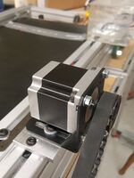
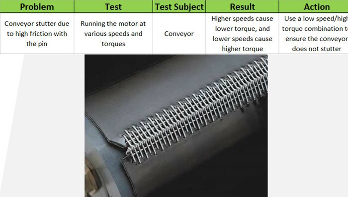
| The Conveyor Belt is driven by a Nema 23 Stepper Motor, which has a maximum torque of 1.8 N-m at 60 RPM or less and a power supply of 24VDC. The transmission to the shaft is provided by the combination of two 3D-printed timing pulleys and a T159 series timing belt. The gear ratio is 2 to 1. | |||||
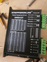
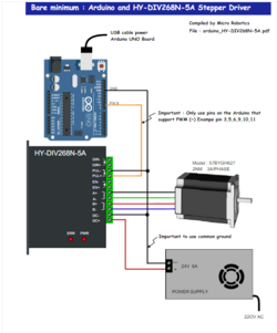
| The Stepper Motor is driven by a stepper, and as is shown in the picture, it can control the Torque and RPM by changing the Pulse rate. The highest Torque will be at 4.20A from the Table. | |||||
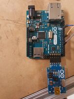
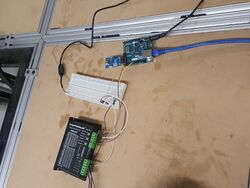
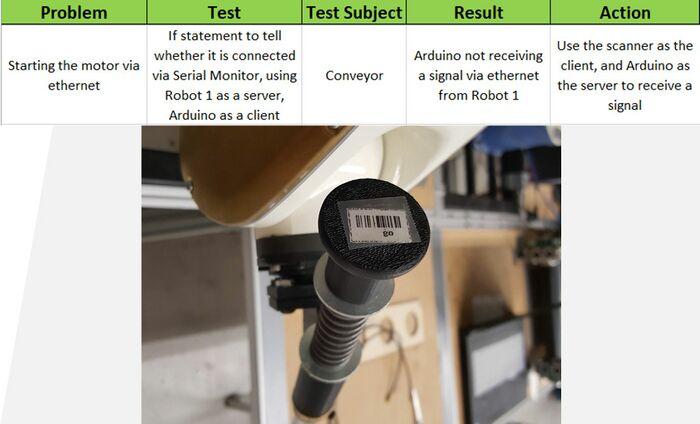
| To integrate the Conveyor in the automated system, we used an Arduino with Ethernet IP function, to be able to connect the conveyor via Ethernet to an already installed hub. | |||||
| Circuit | Diagram | Assembly |
Design Validation[edit | edit source]
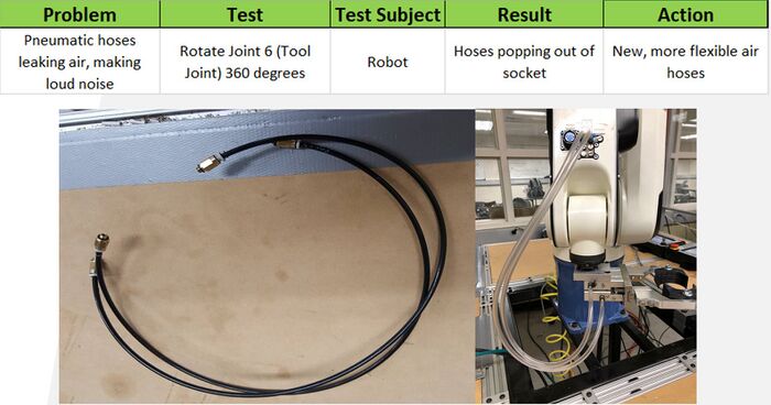
Air Hoses[edit | edit source]
Arduino Connection[edit | edit source]
Conveyor Belt Connection[edit | edit source]
Conveyor Alignment[edit | edit source]
Team Members[edit | edit source]
| Team "CyberCrew" | |||||
|---|---|---|---|---|---|
| Member | Biography | Discipline | |||
| Iulian David | I am originally from Moldova, which is a small country in Eastern Europe. I always liked to disassemble different mechanisms and take a look at what was inside and how it worked, that is why I decided to pursue mechanical engineering. In Moldova I finished 3 years of the Mechanical Engineering program in Technical University of Moldova, then I decided to move to the USA. After a couple years living in the USA, I transferred all my credits to University of Idaho to continue my studying in the same program. Now I am a Senior in Mechanical Engineering program at University of Idaho and I am going to graduate in December 2018. My goal is to obtain the maximum experience and knowledge to be able to invent something new, which will make life easier. | Mechanical Engineering | |||
| Mark Leitner | Coming from Richland, Washington, I grew up in the Hanford area. It seemed everyone who lived around me was an engineer. However, it took me a while to realize that I actually wanted to pursue this. After switching majors a couple times, I realized that I missed math, so I switched into the major my sophomore year. Some eventual goals of mine are to live somewhere warm, travel, and have a job that can support my terrible spending habits. | Mechanical Engineering | |||
| Faihan Aldouseri | I am from Kuwait, which is located in the Middle East. I was born and grew up in Al Ahmadi which has two sides: civilian and industrial. In addition, I graduated from high school and started studying in the famous college of Kuwait starting in 2006. After several years through working as a diesel mechanic and industrial inspector, I realized that I have to complete my studies to improve my knowledge and lifestyle. l like mechanical engineering because I always helped my father to do mechanic stuff on our farm. | Mechanical Engineering | |||
| Abdulmuhsen Alhajeri | I am from Kuwait. It is a small country but there are lots of companies due to the oil we have back home. So, engineering is an important major to learn and bring back home due to the many companies. I chose Mechanical engineering for two reasons. First, because I like working with machines. Second, because this major has a good future. I hope to gain experience as quickly as I can. | Mechanical Engineering | |||
