Dynamic Fish Pond Cleaning System
| Fins for Filtration Team | |
| Sponsors | |
| Team Name | Fins for Filtration |
| Duration | Fall - Spring 2013/2014 |
| Faculty Advisors | |
| Mentor |
|
| Team Members |
|
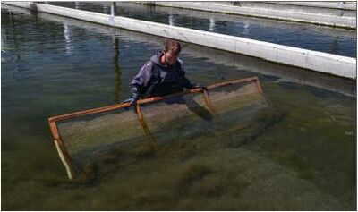
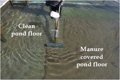
Cleaning fish and food waste from fish hatchery raceways is a problem that has yet to be completely solved. The accumulation of waste is a problem because it can lead to disease and cause other fish health related problems. Fish waste and food particles can accumulate at the bottom of raceways and are easily re-suspended in water by turbulent flow or fish movement. The current method of cleaning fish raceways is a very tedious and slow task that does not clean the raceway 100%. The goal for our project is to successfully create an automatic cleaning system for the raceways that would significantly decrease the human component of cleaning, as well as increase the efficiency of the process and quality of the cleaning.
Design Goals
- Design an automated cleaning system with little maintenance.
- Reduces fine particulate in raceways from accumulating downstream to increase fish health.
- Maintains Current Phosphorous levels and Healthy Dissolved Oxygen levels.
- Analyses of flow using computational and experimental fluid dynamics.
Design Specifications
- Our design must accomplish the following
- Fit within the existing specifications of the raceways (only minor raceway modifications)
- Be more effective than the current system.
- Reduce downstream flow of particulates
- While continuing to produce 5 to 7 cfs of flow in the raceway
- Stay within EPA regulations of flow and waste
- Current EPA standards and regulations: http://water.epa.gov/scitech/wastetech/guide/aquaculture/index.cfm
Project Learning
Background Research
Current Methods
- A push screen that re-suspends particulate from the bottom and sides of the raceway
- A vacuum that cleans waste once it has reached the quiescent zone
Baffle Methods
- Increases the flow at the bottom of the raceway to move waste
- Has been implemented before but due to problems it is not currently in place
Brine Methods
- Injects a solution with a density higher than water and the particulate to float the waste along the bottom to the quiescent zone
- Has been tested in a controlled environment but never in an actual fish raceway
Interviews
Scott Williams, Aquaculture Center
- Scott has previously worked for Clear Springs Inc. and had a vast knowledge of their operations
- Suggested the baffle idea be our main focus due to simplicity and amount of previously tested ideas with same basic design
Ken Cain, Fisheries Immunologist
- Ken has also previously worked for Clear Springs Inc.
- Suggested we move away from baffle idea because it has been tried many times and has never been successfully implemented
- Confirmed that the introduction of a brine solution will not harm fish, but will actually help to kill bacteria in fish gills and scales. We will however have to test the brine method with fish in order to determine the effect fish movement has on brine solution at the bottom of the raceway.
Jim Liou, Hydraulic Engineer
- Provided brine solution research and method
- Has previously used the brine solution method in a controlled environment (without fish)to test how it works as a waste removal system
Visit to Clear Springs
- On November 23rd our design team visited the Clear Springs facility in Buhl, ID. They gave us a tour while we asked questions and discussed design parameters and options. They're facility is primarily a food stock farm (producing fish primarily for food purposes) but it also has a few brude stock (spawning) operations.
- Important design restraints gathered from the trip:
- The flow in each raceway is roughly 7 cfs, it cannot drop to below than 5 cfs or fish in the downstream raceways will start to die
- Current QZ zones are cleaned 1/3 at a time and the water from the cleaning goes into an 8 in. pipe and is transported to a settling lagoon from there
- The furthest upstream raceway is the most sensitive to flow change because it has the youngest fish
- Automated cleaning design would be most effective if it were portable from raceway to raceway, rather than a model being built for each individual raceway
- Cost is the number 1 deciding factor
- They seemed most interested in our baffle idea because:
- Ease of use
- Low cost
- No modifications to the raceway required
- Possibility for adjustments and easy maintenance
- Their thoughts on the movable pump design:
- More effective at cleaning than the baffle
- Would require installation of equipment inside of the raceway
- Outflow would have to be carefully monitored to maintain adequate flow in the raceway
- Could tie into the 8 inch drainage pipe already in place
- Potentially more costly but could clean more effectively and require less man hours than baffle
Concept Development
Baffle Method
- Have tested a simple baffle design in our small flume
- Exploring several new designs
- Multiple baffles
- Baffle with diffuser
- Movable baffle
- This option is our first priority because of its ease of use, cost effectiveness and overall portability
| Type | Parameters | Test Results |
|---|---|---|
| Straight Baffle |
|
|
| Multiple Baffles |
|
|
| Baffle with Diffuser |
|
|
| Moving Baffle |
|
|
Moving Vacuum Method
- We have tested two similar methods for this method
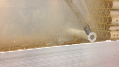
- Both were constructed from pvc and used siphon methods to create a suction along the bottom of the raceway
- First method had small holes along the bottom of our vacuum piece
- Second method had a small slit along the bottom of the vacuum piece
- There was no noticeable difference between the two in terms of suction
- This method is second in priority after the baffle because it is slightly more complex and has the potential to be more costly
| Type | Description | Effectiveness | Discharge |
|---|---|---|---|
| Vacuum 1 |
|
|
|
| Vacuum 2 |
|
|
|
Final Design Development
Movable Baffle
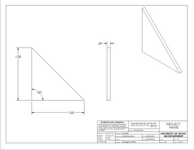
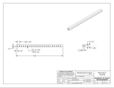
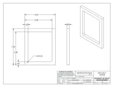
Our final design was a movable baffle, designed specifically for our small scale flume, that was pushed by the force of the moving water along the length of the raceway. We found this to be the most effective and cost conscious method available. The final design was also retrofitted with a removable horizontal baffle that extended the distance between the baffle and the cleaning front of the fish bio-solids. This design was displayed at the Engineering Expo by our team on May 2nd. Our team won best technical presentation and judges choice best booth presentation for the work completed.
| Part | Description |
|---|---|
| |
| |
| |
|
- Trial 1 with the movable baffle design, tested with a 0.25" baffle gap
- Trial 2 with the movable baffle design, tested with a 0.5" baffle gap
- Trial 3 with the movable baffle design, tested with 0" baffle gap
- Trial 4 with the movable baffle design, tested with 0" baffle gap and 9" horizontal baffle
- Trial 5 with the movable baffle design, tested with 0.25" baffle gap and 9" horizontal baffle
Design Documents
Meeting Log
File:2014 Fins Meeting Log.pdf
Technical Presentation
File:2014 Fins Technical Presentation.pdf
Final Design Report
File:2014 Fins Final Report.pdf
Team Members
Jeremy Schroeder
Mechanical Engineer
Hometown: Aberdeen, ID
School Status: Senior Graduating in May, 2014
Hobbies: RC airplanes, wood-working, rock climbing
Technical Interests:Fluid mechanics and CFD's
Kate Wicher
Environmental Engineer
Hometown: Boise, Id
School Status: Senior Graduating in May, 2014
Hobbies: Running, yoga, language learning, and hiking
Technical Interests:Environmental Chemistry
Matt Francis
Environmental Engineer
Hometown: Idaho Falls, Id
School Status: Senior Graduating in July, 2014
Hobbies: Skiing, fly fishing, and whitewater rafting
Technical Interests:Wastewater and enviromental protection
Levi Dawes
Eco-Hydrological Engineer
Hometown: Princeton, Id
School Status: Senior Graduating in December, 2014
Hobbies: Hunting, fishing, and snowboarding
Technical Interests:Hydraulics and hydrology

