Prosthetic Liner Donning Device
| Prosthetic Liner Donning Device | |
| Sponsors |
|
| Team Name | Snap Into Motion |
| Duration | Fall 2013 - Spring 2014 |
| Faculty Advisor | Dr. Tom Hess |
| Mentors |
|
| Team Members |
|
Snap into motion is a senior capstone design team that is dedicated in designing a system to enable independent liner donning for transtibial amputees. Our project is to design a device to aid lower limb amputees in donning their prosthetic liner. The device will ensure that the liner sits flush against the limb, properly aligns the pin into the prosthetic, and enables those with low hand dexterity, vision, or flexibility to don their liner independently.
Design Task
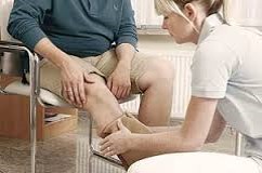
| Nurse Helps Transtibial Amputee with Donning Prosthetic Liner |
|---|
There are approximately 34,000 transtibial amputations performed each year in the United States. The causes of these amputations range from infection to tumors with the most prevalent causes being diabetes and severe traumatic injury. Patients with transtibial amputations that wish to use a prosthetic leg must wear a prosthetic liner that protects their skin from the rough prosthetic leg materials and helps suspend their leg in the prosthetic. Prosthetic liners can be difficult to don, especially for patients with limitations in flexibility, hand dexterity, or vision.
Our goal is to create a mechanical system that will allow patients to independently don their liner and:
- Comfortable
- Easy to use
- Work with commercial liners/prosthetic components
- Accommodate the majority of patients
- Reduce strain for the patient
- Require little to no hand strength or dexterity
- Aid inflexible individuals
- Properly align the pin
Design Specifications
|
Project Learning
Background Research
Dimensional Analysis of Transtibial Roll-On Style Prosthetic Liners
- Distal diameter ranges from 2.5" to 12.0"
- Proximal diameter ranges from 3.1" to 12.0"
- Target lenght of liners ranges from 12.0" to 16.0"
- Pin lengths have a standard diameter of 10 mm, standard pitch of 1.5 metric, and varying lengths from 1" to 2.25"
Interviews
| Interviewee | Overview |
|---|---|
| Lisa Huffman
Client Interview on 10/3/2013 |
Background Information on Patients
|
Concept Development
Drive Design Alternatives
| Design | Description | Pros/Cons |
|---|---|---|
| Parallel Track System
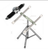
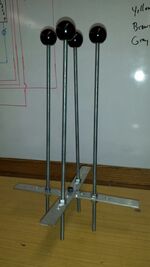
For this concept, a quadpod would be used so that the user could adjust the height to accommodate the level at which users may be sitting. The track would be mounted using a pivot joint to account for the angle at which the user would be sitting. The parallel tracks would be attached to arms. The tracks would use a rack and pinion system for motion. The prosthetic liner would be folded over the arms and, as the tracks moved linearly toward the user, the liner would be donned on the leg. |
Pros:
Cons:
| |
| Linear Actuating System
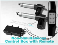
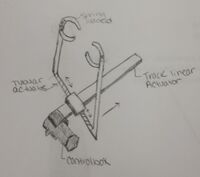
Similar to parallel track system, however, instead of using a rack and pinion system, linear actuators would be on each side of the user with arms mounted to them. The arms would have expanding capabilities to accommodate the change in circumference of the residual limb. Using non-simultaneous donning, the device would mimic the hand motion most often associated with donning; one hand pushes up at a time. Through limited testing, the non-simultaneous donning proved to require less force to don. |
Pros:
Cons:
| |
| Glider Track System
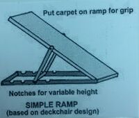
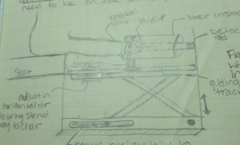
This concept utilizes and exterior approach rather than the interior approaches discussed with the previous design alternatives. The glider donning system utilizes a carriage that glides along a single track. Attached to the carriage are two horizontal actuators which function to move the garter hands onto and off of the liner. The garter hands are spring loaded so that they can accommodate the width of the residual limb. The whole system is attached to a ramp that can adjust to different heights according to the user's chair height. |
Pros:
Cons:
|
Garter Design Alternatives
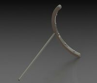
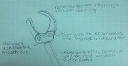
A garter is what we have named the device that will be mounted on the end of the device's arms and will be the part of the device that comes in direct contact with the patient's liner. It is named a garter because it needs to expand and accommodate different sizes of the leg.
| Garter Alternative | Overview |
|---|---|
| Multiple Finials |
|
| Crescent Shape |
|
| Donning Hand |
|
Design Decision Matrix
We compared the drive design concepts in a design matrix that was scaled from 1-5. Based on the matrix, we decided to follow through with the glider track system with the donning hand. Below is the link to the design matrix:
Concept Testing
| Test Photo | Overview | Results |
|---|---|---|
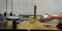
| Force Test on Donning Liner
A fish scale is being used to measure the force required to don the liner using two hands that are attached to the scale at the wrists using string.
|
Four tests were completed and the average of the force at each two inch mark was compiled.
The results can be found in the link below: |
Final Design
Design Specifications
Whole System
After more project learning and design, we arrived at a final design.
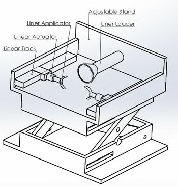
The subsystems include:
- Linear Track & Linear Actuator
- Linear Applicator
- Adjustable Stand
- Liner Loader
A diagram showing how the donning process will work using this design is shown below.
Updated Specifications
| General Requirements | Specific Requirements | Target Values | |
|---|---|---|---|
| Size | Dimensions (LxW) | 36" x 26" | |
| Physical Characteristics |
|
| |
| Components (Manufactured) |
|
.
.
| |
| Components (Purchased) |
| ||
| User Requirements |
|
| |
| Lifespan |
|
| |
| Performance Characteristics |
|
| |
| Environmental Requirements |
|
|
Subsystem Concept Development
Linear Applicator
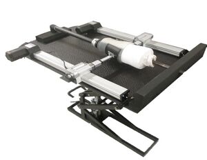
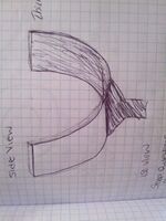
The two linear applicators are what will be in contact with the prosthetic liner and move it up the user's residual limb. There will be pressure sensors that will measure the pressure being applied to the liner/residual limb so that no discomfort or pain will come to the user.
|
Material Aluminum Width 4" Radius 4.22" Thickness .125" |
Linear Track & Linear Actuator
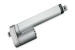
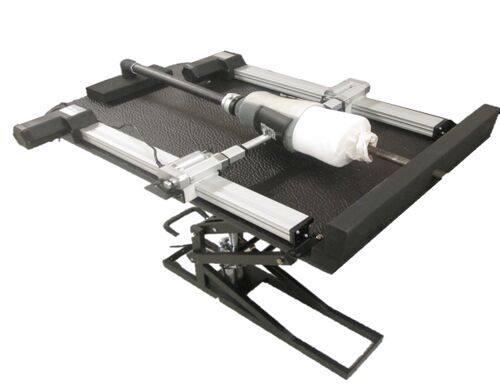
There will be two linear tracks on either side of the stand. The tracks will move towards the user's hips during the donning system while the linear actuators move towards the user's residual limb simultaneously to move the prosthetic liner up the residual limb. Once the pressure sensors that are on the linear applicators reach a certain pressure, the linear actuators will move off of the limb and the linear track will move away from the user approximately 1 inch. This process will continue until the liner is fully donned.
Linear Track
Linear Actuator
Adjustable Stand
The adjustable stand will allow for people to set the device at a height that is comfortable for them. It has yet to be decided if this will be at an angle,using a scissor stand, or both integrated together.
Liner Loader
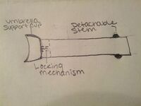
The liner loader is where the user will place the prosthetic liner before the donning process begins. The liner's pin will be guided and locked into the liner loader and then inverted over the liner loader. The liner loader will be a detachable stem so that this is can all be done free of the rest of the donning system. The liner loader is then locked into the stand using a locking mechanism at the end of the stand.
Control System
We will be using an arduino uno microprocessor as our control system. The pressure sensors on the linear applicators will be our input and as an output, the microprocessor will control the movements of the linear track and linear actuators.
Final System
Project Budget
| Linear Actuators (2) |
$109 each x 2 = $218 |
| Track Actuators (2) |
$140 each x 2 = $280 |
| Control System |
$100 |
| Liner Loader |
$100 |
| Adjustable Stand |
$500 |
| Total |
$1158 |
Team Members
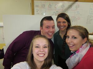
| Pictured left to right:
Top: Matt Guthrie and Samantha Sutherland Bottom: Jennifer Rainey and Jordan Simonson |
|---|
|
Matt Guthrie Mechanical Engineering Student Email: guth0637@vandals.uidaho.edu I am a mechanical engineering student with a passion for prosthetic improvement and an interest in biomechanics. Ultimately I will strive to invent systems that will benefit people around the world. My interests include: playing piano (music in general), skiing/snowboarding, and machining. | |
|
Jennifer Rainey Biological Systems Engineering Student Email: rain5140@vandals.uidaho.edu I am a biological systems engineering student at the University with an interest in medical device development and production. I have interned with a Lead-Lok, Inc., a biomedical innovations company out of Sandpoint, Idaho for the past three summers. I hope to use this background experience to start a career in the medical device industry. I enjoy hiking, kayaking and reading. | |
|
Jordan Simonson Biological Systems Engineering Student Email: simo6466@vandals.uidaho.ed I am a biological systems engineering student here at the University of Idaho and I am extremely interested in how the human body works and how we can improve it to work better. I hope to invent products that make the quality of life better for every single person. For fun, I like to go skiing and play fetch with my puppy. | |
|
Samantha Sutherland Biological Systems Engineering Student Email: suth6834@vandals.uidaho.edu I am a senior at the University of Idaho graduating May 2014 with a degree in Biological System Engineering. For the past two years I have been working as an engineering intern in the research and development department at Schweitzer Engineering Laboratories. Upon graduation, I plan to join a medical device manufacturing company. |
Document Archive
- Project Schedule/Gantt Chart
- Meeting Minutes
- Design Review Presentation
- Design Matrix
- Liner Donning Force Test Results
- Detailed Design Review
- Technical Presentation
- Poster for Expo
- Final Design Report
References:
