SolidCAM Fixtures
This page provides a basic tutorial on loading and defining fixtures for the CNC machines in the machine shop. SolidCAM contains a collision recognition feature that will insure the cutting tool won't run into anything defined as a fixture. Pictures must be double clicked to be resized larger for a more detailed view.
WARNING: If the fixture parts and stock in real life are assembled differently than in the model, the machine may still run the tool into them. An adequate clearance can be selected in the program to account for slight variations.
| Tool/Step | Description |
|---|---|
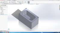
| 1.Draft the Part to be Cut Out. When the CNC part is complete, save the part and open a new assembly | |
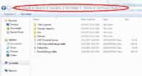
| 2. Determine the Fixtures Needed to Secure the Part to Table. The Solidworks fixture parts are located on the University of Idaho shared drive under shown file path. | |
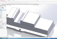
| 3. Locate the CNC fixture Parts and insert the desired fixture part. For the vice, insert vice part (1-01) first. | |
| 4. Insert the sliding portion of the vice and use mates to assemble as shown.
(Note: Mate the the movable vice clamp to the part once it is inserted.) | |
| 5. Insert the parallels (if needed) and select an appropriate height from the design table.
(Note: The parallels used in Figure 5 are 1.25” high.) | |
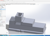
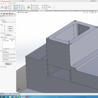
| 6. Insert the part to be cut and mate it to the fixtures.
(Note: Account for stock dimensions when applicable). | |
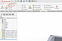
| 7. Once the part is mated to the fixture, click into the SolidCAM tab in SolidWorks and select 'New' in the SolidCAM tab, then 'Create New Operation'.
(Note: In this case, milling is selected). | |
| 9. Select the external save option and click the green check mark. Set the coordinate system by clicking the 'CoorSys' button. | |
| 11. Select the appropriate face for your part and click the green check mark once the axes are selected correctly. | |
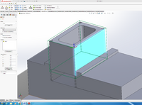
| 12. Select the stock for the part by clicking the stock button. Select the part and a green square will appear around the part you have selected. If the green box is around the fixture as well as the part, it means the fixture was accidentally selected. | |
| 13. Change the size of the stock using the areas in the left hand toolbar. When the stock is defined, click the green check. Click the green check once more to leave the setup menu. | |
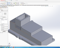
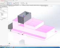
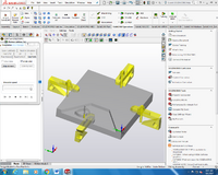
| 14. Find the fixtures tab on the design tree and click 'Define Fixture', then select all the necessary fixture parts. Click the green check mark when all the fixtures have been selected. After the fixture has been defined, click the setup tab and a table will appear. Under the fixture column, double click the drop down boxes and select 'Clamping Fixture'. You can right click the drop down tab and click 'Show (3D)' to double check that SolidCAM recognizes the fixture. | |
| 15. Open iMachining and start a new 3D operation. | |
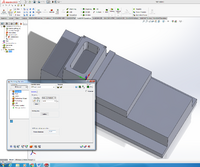
| 16. When setting up the operation be sure to check the box for 'Fixture Collision Recognition'. Also be sure to set an appropriate fixture clearance in the 'Fixture Clearance' box. | |
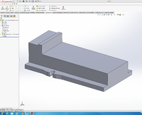
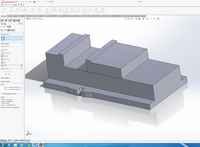
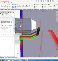
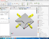
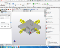
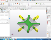
| 17. When finished defining the operation, calculate the path (this may take a while). After it is done calculating, the simulate button can be used to double check that the tool does not collide with the fixture. An example of this can be found in the figures below. The part shown below is an arbitrary example used to show the fixture recognition. This fixture set-up would obviously not be wise in an actual machining environment but is makes it obvious that the software recognizes that the tool is not allowed to hit the fixtures. | |
| Confirm that the correct parts were selected as fixtures in the dialogue box that pops up once they are defined. The threaded shafts, and their nuts have their dimensions dictated by a design table.
(WARNING: Stock and Fixtures must be measured on actual machine when they are placed into the assembly to insure the program will not run the tool into them! If the program doesn't give the right amount of clearance for the actual part compared to the SolidWorks model, it will still run into it! The angle the T Bars and Triangles make when fit together may need to be accounted for in assembly!) | |
| Figure 17 shows the simulation of the calculated code, which demonstrates the program recognizing that the tool should not collide with the fixture. (Fixture clearance of 0.01”) | |
| Figure 18 shows an early stage in the simulation | |
| Simulation Progress | |
| Simulation Progress | |
| Simulation Progress | |
| Simulation Progress (close to end) | |
| Simulation Complete, green indicates stock that was left over after the cut. The machine was originally programmed to cut out the parts left over under the fixtures, but didn't due to the process defined in this guide. |
