3D Printing for Metal Components
| Sponsors |
|
| Team Name | VandalForge |
| Duration | Fall 2016 - Spring 2017 |
| Advisors |
|
| Students |
|
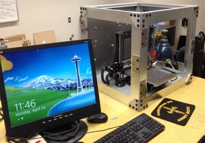
The goal of the project is to design and create a cheap and effective 3d printer which can print metal components, by integrating the technologies present in plastic 3d printing, and MIG welding.
Problem Definition
Background
With the technological advances in the field, 3d printing has recently become very popular, but one major drawback to these machines is that they can only print in plastic. Plastic 3d printing has many uses, but there are many applications where, whether due to temperature, high stress, or other reasons, plastic doesn't suffice. There are currently a few metal 3d printers on the market, but they can cost tens or even hundreds of thousands of dollars, putting them out of the price range of many.
Deliverables
A device capable of precisely and effectively printing steel components and costing less than $1500.
Specifications
- Project Specifications (As of 11/3/2016)
- Print Volume - 8x8x7 in.
- Resolution - 150% of Electrode Size
- Print Speed - 100-200 mm/s
- Electrode Size - .025 in.
- Plate Thickness- 1/8 - 1/16 in.
- Input Voltage - 120 V
- Exterior Temp. - 110 F
- Cost - $1500
- Total Size - 36x36x36 in.
- Layer Thickness- 25% of Electrode Size
- Wire Feed Rate - 40-500 in/min
- Output Amperage- 10-50 A
Project Learning
Client Interview
- Wrote a list of questions for our client in order to ascertain the parameters we needed to meet, those we would like to meet, and those we could try for if time permitted.
- From the answers we were able to compile a list of design parameters to meet.
Lead Instructor and Technical Advisor Meetings
- Every week we meet with our lead instructor/client to go over the previous week's project and ask any questions we needed answered.
- Every week we had another meeting for just the team, this is where we discussed the project, and made most of our final team decisions.
Research
To start this project, our team broke into two subsections, the CNC team, responsible for the 3d printer and attached code, and the Welder team, responsible for the welding apparatus and the power supply which drives it.
- CNC
- The CNC team quickly settled on the idea of findng an open-source printer to use rather than designing a system from scratch, and not long after that decided to source our own parts for it rather than buying a kit, so we didn't have to pay for the systems like the bed and the extruder which we weren't going to use. We looked at a variety of open-source printers, but eventually settled on the P3Steel, a steel-framed variant of the Prusa i3.
- Welder
- The first decision we faced was whether to purchase a commercial welder and modify it, or to create one of our own. We eventually settled on creating our own, because our power requirements were so different from that of a standard welder. We did decide, however, to make use of some parts of a commercial welder, specifically the weld cable, and wire feed system. We will be designing our own circuitry based on a commercially available microcontroller and power supplies, our own gas shielding system, and our own printhead/extruder.
Design
Microprocessor
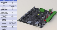
The microprocessor we selected for our project was the Smoothieboard. It has enough ports on the board to support the stepper motors which will drive the machine, and room for a wide variety of sensors which will assist in the feedback controls that will allow the printer to operate effectively.
Programming
It was determined early on in our project, that the creation of new software for wasn't an option, both because of our team's relative inexperience and the sheer amount of time this would've entailed. Instead, we decided to use open source 3D printer softwares and modify them to suit our needs. There are three discrete pieces of software needed to operate any 3D printer. First, is the Computer Aided Design (CAD) program, this is what is used to design the part which the printer will create, however users can skip this step by downloading files for a part someone else has designed. The second piece of software is the slicer, this program slices the 3D model into individual layers, and determines the path the printer will take to create the part. The file the slicer generates is then exported to the third and final piece of software, the microprocessor firmware; this is the program that is loaded onto the printer itself which interprets the files into motor commands for the printer to follow. Our project required us to make changes to both the slicer and the firmware, in order to correct certain variables like wire feed rate, and print speed.
CNC
This project utilizes the CNC functionality of the P3Steel, while removing the stock bed and plastic extruder. These compontnents will be replaced with others which are capable of generating and withstanding the conditions under which the printer will be operating. Modifications to the stock printer will also include the replacement of many, if not all, of the plastic features with machined metal equivalents due to heat and fire risks.
- Wire-Cutter
- Two potential source of inaccuracy in the printing process are non-constant wire stick-out lengths (the length the wire sticks out past the contact tip of the welder) and excess buildup of metal at the conclusion of a weld. Both of these problems are being mitigated by the addition of a system which will be used to re-zero the stick-out of the welder by cutting off any excess length and/or buildup before a new weld is started. This will be accomplished by mounting a small DC motor on the X-axis connected to a grinding wheel, then, when the microcontroller commands, the printhead will move to the cutter, and the DC motor will activate, cutting the wire to a uniform length so the print can continue. The excess wire will be collected via a magnet positioned below the wire-cutter system which will function so long as the amount of wire being removed is small, should wire buildup on the magnet become a probelm, a new approach for wire collection will be devised.
- Printbed
- One of the requirements for MIG welding is to have an electrically grounded plate, this makes traditional 3D printer beds of glass or plastic unsuitable as they are electrical insulators, and don't posess the thermal properties required for welding temperatures. For this reason, we chose to design and build a custom printbed from aluminum with steel sheet inserts, this should provide the necessary heat dissapation, as well as making replacemnt of the steel sheet (which is required after each print) as painless as possible. One of the major difficulties encountered in this design, is that the steel insert tends to warp and pull away from the aluminum base during welding operations, which makes the printing process less accurate. This problem of warping is magnified by the fact that once the sheet lifts, much of the heat transfer capabilities of the system is lost, meaning that once warping starts, it only gets worse.
Welder
A MIG welding apparatus can largely be seperated into three distinct, but equally important parts, the gas system, the printhead, and the power supply.
- Gas System
- The MIG in MIG welding stands for "Metal Inert Gas" and this section will be discussing the inert gas portion. To create quality welds with a MIG welder, the weld bead needs to be shielded by inert gas, we will be using a 75%/25% mixture of Argon and Carbon Dioxide. The purpose of the gas system is to move this shielding gas from the tank to the printhead, and to diffuse the gas over the weld, the microprocessor will be given control of the gas flow rate by way of a motor-controlled valve, in order to create the best welds possible while using as little gas as possible. In addition to this, the gas flow rate can also be used to modulate the temperature of the weld, an important variable for ensuring an accurate, non-warped final product.
- Printhead
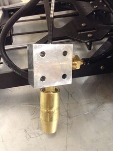
- The printhead is where the wire-feed, the welding power, and the inert gasses are all brought together, the design incorporates aspects of both a standard 3-D printer printhead, and a MIG welding gun. This block will be mounted to the printhead carraige, and functions as the welding gun for our printer.
- Power Supply
- The power supply is what draws electricity from a conventional wall outlet, and outputs electricity at the specifications needed to operate the welder. For this project, we opted to buy an off-the-shelf welder for its power supply, as designing our own would've been costly and time-consuming.
Safety
Due to the potentially hazardous nature of this project, one of the most important design factors we have been considering is safety. This safety can be broken up into two sections, internal safety, keeping the more sensitive parts of the machine safe from harm, and external safety, keeping the user safe from harm.
- Internal Safety
- Due to heat concerns, most of the plastic parts of the printer have been replaced with metal, however, for some parts this is either impossible or impractical, the focus therefore becomes shielding these parts from both excess ambient heat, and hot debris from the welding process. The parts most at risk within the printer chamber are the electronics, specifically the motors, switches, and the wires that connect them. To mitigate problems arising from the high ambient heat associated with welding in an enclosed area, a fan system is being installed to vent the hot welding gasses, and conduits have been installed to shield the wires from any welding spatter.
- External Safety
- The first step to making this project safe for the consumer is the complete enclosure of the welding area, which will prevent errant sparks from causing injury and starting fires. Another danger of welding is the light produced, which can cause serious ocular damage if looked directly at, which is why the sides of the welding enclosure will be made of welding curtain, a material specifically made to block the worst of the light produced.
- Alongisde these passive safety measures, some active safety measures have been discussed. The first of these, which will definitely be implemented is a kill-switch fitted into the lid of the box, so if the box is opened while the print is in progress, the gas will shut off, and all power to the printer and welder sub-systems will be turned off. The printer will also be fitted with a manual kill-switch on the outside of the box, which will have the same result. Another active safety system will see thermocouples installed on the outer walls of the enclosure to ensure they stay within a non-dangerous temperature range.
- Another discussed safety system would function as a fire supressant. In a situation where either one of the few plastic parts of the device caught fire, or something flammable was put into the print enclosure, a detector would notify the processor of the fire, and a system similar to the kill-switch would activate; but in this case, the ventilator fan would also be shut down, and the gas tank would be opened up, flooding the enclosure with Argon and CO2 which would smother the fire. This system is still hypothetical for now, and regardless whether or not it is implemented, a fire-extinguisher will be mounted to the side of the printer at all times.
Team Information

|
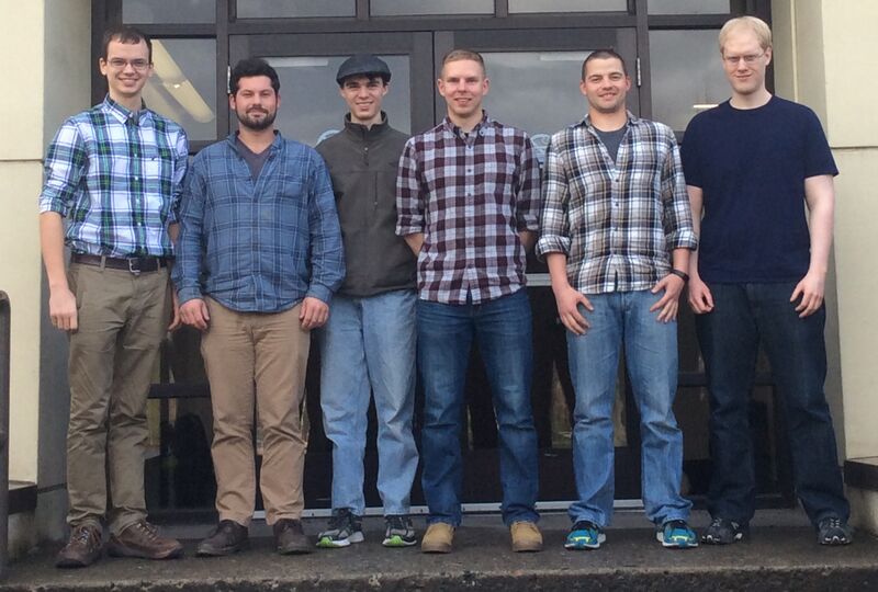
| Team members listed below from left to right |
|---|
| Nathan Wagner | Project Specialty: 3d printing, safety features |
| Mechanical Engineering | |
| Email: wagn4580@vandals.uidaho.edu | |
| Kyle Krieg | Project Specialty: Power electronics, Programming |
| Electrical Engineering | |
| Email: krie3260@vandals.uidaho.edu | |
| Peter Haley | Project Specialty: 3d printing |
| Mechanical Engineering | |
| Email: hale2575@vandals.uidaho.edu | |
| Maxwell Emerson | Project Specialty: Welding |
| Mechanical Engineering | |
| Email: emer6763@vandals.uidaho.edu | |
| Matthew Buchanan | Project Specialty: Welding |
| Mechanical Engineering | |
| Email: buch1496@vandals.uidaho.edu | |
| Jay Van Gerpen | Project Specialty: microcontrollers, Programming |
| Electrical Engineering | |
| Email: vang9902@vandals.uidaho.edu |
Document Archive
Preliminary Design Review
Detailed Design Review
Expo Poster
Design Report


