Doubly-fed induction generator (DFIG)
| [[File:|300px|center|alt=]] | |
| Team members | |
| Team Name | Dang! the Fan Is Going |
| Duration | Spring 2019 - Fall 2019 |
| Faculty Adviser |
|
| Team Members |
|
The goal of the project is to build a motor generator system that mimics a wind energy system, which is based on a Type-Ⅲ DFIG, the main task is to design a controller for the rotor side that will enable the machine to turn at a very low frequency, but generate at 60 Hz using a variable speed drive system.
Background[edit | edit source]
The doubly fed induction generator (DFIG) wind energy system is widely accepted in
today's wind energy industry. The DFIG is essentially a wound rotor induction generator
in which the rotor circuit can be controlled by external devices to achieve variable
speed operation. The stator of the generator is connected to the grid through a transformer,
whereas the rotor connection to the grid is done through power converters, harmonic
filters, and the transformer.
The stator of the generator delivers power from the wind turbine
to the grid, as for the rotor, the power can be delivered from the rotor to the grid and vice versa through rotor-side converter
(RSCs) and grid-side converters (GSCs).
Deliverables[edit | edit source]
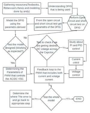
The major task for the first semester is to understand the DFIG and measure the parameters of the machine our team use in the power lab. The task for the second semester is to successfully model and design appropriate control system required to achieve constant DC voltage across the Capacitor used even at low frequencies.
Specifications[edit | edit source]
Generate constant 60Hz power at different low frequencies.
Should be capable of functioning in both sub-synchronous and super-synchronous mode.
Design Considerations[edit | edit source]
The DFIG is a type of induction machine, so the locked-rotor test, the no-load test and the DC test need to be performed to measure the parameters, to check if the parameters make sense, we can test the machine with variable loads to come up with a torque-speed curve, and use it as a reference to see if the torque-speed curve from the simulation using parameters derived from tests matches.
Current-controlled Real/Reactive Power Controller with a Controlled DC-Voltage Power Port in dq-frame
Project Learning[edit | edit source]
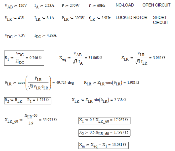
Since our team members weren't really familiar with DFIG, we had to do a lot of readings and researches to get the ideas of how DFIG works and control over it. Also, it is a hard project that was out there for several semesters and even graduate students worked on it, our progress can be very slow. We took three weeks in the power lab to test the machine in sub-synchronous and super-synchronous mode and did the locked-rotor test, the no-load test and the DC test. Below is the result we got for our first parameter tests.
Previous project revising[edit | edit source]
Starting from the second semester, our team focused on both hardware and software by first revising previous project done by graduate students and former senior design teams.
For the hardware, we looked at a grid side converter(GSC) design built by Rebecca Dong, it consists of power converter module, DC/DC converter, voltage/current sensor and a single 16V power supply. We came up with a brief schematic of this GSC and learned the function of each component of the board, even though our goal is to design a converter for the rotor side, we can still use it as a reference.
However, this board is too complicated, we want to build a controller system with multiple boards perform individual tasks, so we turn to a project done in 1996 led by Dr.Joseph Law, this project is a controller system for a induction machine, we particularly looked at the gate driver delay circuit and the gate driver board. In the delay circuit, 2 sets of input go into 1 of the 3 lines that are used to drive the gate of the power converter, the purpose of the delay circuit is to prevent the situation when the upper and lower transistor of the inverter closed at the same time to cause a short around the DC bus. The delay circuit then sends its output information to the gate driver board through fiber optics to eliminate the interference of other equipment in this system. The gate driver board converts fiber optic light signals to pulse signals to trigger the transistor and provide reference for the emitter on each of the transistor.
Field orientation Control[edit | edit source]
Using an already provided assembly language for a squirrel cage induction machine partial c++ code was developed that can be used in conjunction with hardware decided to use in the future.
PID control[edit | edit source]
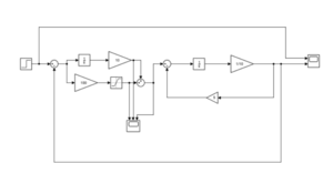
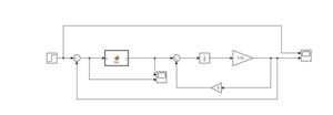
To start we first developed a simple RL circuit with current across the inductor as output and simple step function as voltage input and developed simulink Matlab files for it. In future using the simulink files provided by DR. Law, which can be found in project portfolio Matlab code needs to be developed in simple C/C++ language that can be easily imported to any hardware decided to use.
Conclusion[edit | edit source]
The goal of the project was to model a wind-energy system based on type-3 DFIG. In the Spring semester we studied DFIG and conducted tests to get the parameters of the machine being used. In the Fall semester we tested existing hardware and back tracked the circuitry of the hardware and documented the progress. We also learned about space-vector and dq axis. Used existing assembly language code to develop a simple C++ code and started working on the PID control.
Future work[edit | edit source]
Some of the future work that can be done on this project are:
Develop a MATLAB version of Field Oriented control.
Design fully functioning gate drivers.
Design current and voltage sensors
Test the designed hardware.
Design three phase switch power electronics converters (both thermal and electrical).
Team Members[edit | edit source]
|
Xin Han | |
|
Zhengqi Li
| |
|
Manasa Pathamsetty
|
CPM Chart[edit | edit source]
Meeting Minutes[edit | edit source]
File:Minute-1 Han 02 12 2019.pdf
File:Minute-2 Li 02 19 2019.pdf
File:Minute-3 manasa 02 26 2019.pdf
File:Minute-4 Li 03 07 2019.pdf
File:Minute-5 Han 03 26 2019.pdf
File:Minute-6 Manasa 04 02 2019.pdf
File:Minute-7 Li 04 02 2019.pdf
File:Minute-8 Han 04 11 2019.pdf
File:Minute-9 manasa 04 23 2019.pdf
File:Minute-10 Li 09 03 2019.pdf
File:Minute-11 Han 09 10 2019.pdf
File:Minute-12 Li 09 18 2019.pdf
File:Minute-13 Li 09 27 2019.pdf
File:Minute-14 Han 10 01 2019.pdf
File:Minute-15 Li 10 09 2019.pdf
File:Minute-16 Han 10 22 2019.pdf
File:Minute-17 Han 11 12 2019.pdf
File:Minute-19 Li 11 20.pdf
File:Minute-20 Han 12 10 2019.pdf
Presentations[edit | edit source]
File:Snapshot ppt.pdf
File:Design review.pdf
File:Expo presentation poster.pdf


