Excitation Control for a Synchronous Generator
| Excitation Control for a Synchronous Generator | |
| Sponsor: | Schweitzer Engineering Laboratories |
| Team Name: | Three Phase |
| Duration: | Fall 2014 - Spring 2015 |
| Faculty Advisor: | |
| Technical Advisor: | |
| Students: | |
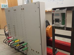
The goal of the project is to establish a static excitation system for the synchronous generator in the University of Idaho Model Power System (BEL Power) Lab. Students will need to specify, install, and commission the exciter, including user documentation and a verified RTDS system model.
Background
Exciter Overview
An exciter is a control system that adjusts the magnetic field of a generator. It is capable of monitoring the AC output of a generator and feeding a DC current back into the generator's field. The exciter uses system measurements and control logic to determine if the generator’s AC output is deviating from its desired rating. If a deviation is found, the exciter readjusts the DC current being fed into the field. This process ensures that the generator's output remains stable and at the desired value.
Depending on how the generator is connected to the system it may either control the bus voltage or it may inject reactive power into the system. It is common for modern exciters to be able take system measurements and regulate either the reactive power or voltage output of the generator based on a user dictated regulation mode.
There are two types of exciters, static and rotating. A static exciter is physically independent of a generator and requires a power source (can be the generator's output or some other external source). A Modern static exciter uses a rectifier and controller to convert the AC source into a DC output for the field. The static exciter contains no moving parts and receives its name from the stationary nature of the system. The second type of exciter is the rotating exciter. The rotating exciter uses a DC machine that is connected to the rotor shaft to generate a DC voltage that can be amplified or attenuated for use in the field. The rotating exciter receives its name due to the fact that is has components in motion by rotating.
The excitation system of a synchronous generator is the main equipment of operation and control of generators and the power system. According to experiments (Li, L., Caixin, S., & Daohuai, M. 2005), more than fifty percent of all the faults of the generator are because of the excitation system. Finding the tiny fault of the excitation system in time and making adjustments is important to ensure the safety of the generator group and power system.
Generator Overview
Synchronous generators have an additional coil on the rotor that will help pull the rotor and generator into synchronization. Also they only produce torque when the rotor is not turning at synchronous speed. The amount of current depends on the frequency difference between the stator and the rotor. The equation to get the voltage terminal of the generator is the following: <math>Vt=Ra*Ia+j*Xs*Ia+Ea</math>. To calculate the current on the field, a no load measurement of the current needs to be done first. Since at no load <math>Ea = Vt</math> Then solving for the constant <math>kw = Ea(no load)/If(no load)</math> using the equation to calculate the voltage terminal we can find Ea and using the following equation <math>If = Ea/kw</math> we could find the current of the field.
Problem Definition
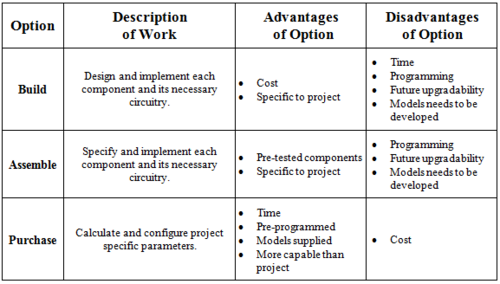
In this project it is desired that Three Phase either design, assemble or purchase a static exciter. The Exciter must be capable of fast field forcing to temporarily increase the generator's AC output voltage during voltage sags caused by simulated faults. The exciter should also provide closed loop regulation of the generator's AC output voltage during normal operating conditions.
Specifications
| Specific Requirement | Description | Target | Acceptable Performance |
|---|---|---|---|
| Size |
The exciter must be capable |
18" x 27" x 32" |
All dimensions |
| "Normal"
Operating Range |
The output of the exciter |
3-6 Amps DC |
Can sustain 6 Amps or Better |
| Generator Output |
The exciter should adjust |
220 Volts AC | +/- 1 Volt of Target |
| Forcing Output |
The exciter must be capable |
Up to 24 Amp DC |
Can sustain 24 Amp DC |
| Generator Starting |
The exciter needs be able |
A battery can be used |
The exciter can start the |
| Display |
The exciter should be capable |
Field Current |
Field Current |
Design Decision Comparison
Exciter "Buy" Options
Product Comparison Matrix
The UNITROL-1020 was selected for this project. Since all products have greater capabilities than necessary for this project, ABB was chosen to remain consistent with the VFD being used in the lab.
| Features | ABB Unitrol - 1020 |
Basler DECS-250 |
Reivax RTX Energy DRV01 |
|---|---|---|---|
| Maximum Input Voltage |
300 Vac | 277 Vac | 220 Vac |
| Exciter Output | Up to 20 Adc | Up to 15 Adc | Up to 20 Adc |
| Short Term Overload |
Up to 40 Adc Up to 10 seconds |
Up to 30 Adc Up to 10 seconds |
Up to 40 Adc Up to 30 seconds |
| VR accuracy | +/- 0.20% | +/- 0.25% | +/- 0.10% |
| Operating Temperature | -40 to 70 degC | -40 to 70 degC | 0 to 70 degC |
| Interface |
USB |
USB |
Ethernet |
| Size | 6.69" x 6.69" x 11.89" | 8.08" x 8.62" x 12" | 11.8" x 23.6" x 31.5" |
Digital Simulation Model
Models
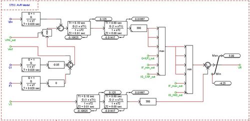
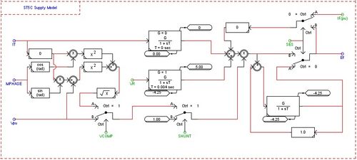
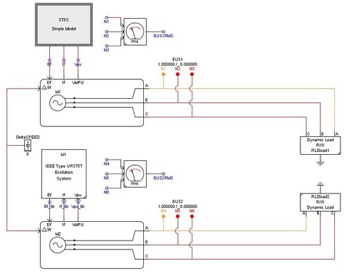
The models and default parameters in this section are directly from ABB's document ZAB-3BHS223093-E62 for use in an RTDS simulation. The models provided by ABB were translated into RSCAD software for use in future projects and research.
|
ST5C AVR MODEL
|
|
|
ST5C SUPPLY MODEL
|
|
|
URST5T MODEL |
RTDS Testing
|
|
|
In general we can see the same response from the models. The ST5C (left):
(Note: The Waveform on the right was varied a moment before the waveform on the left) |
Further Verification
The digital simulation model has a similar response to the library exciter model, but it has yet to be compared the the physical UNITROL-1020. To fully verify the digital simulation model the PID controller of the UNITROL-1020 will need to be tuned for the generator. The new values, after tuning, will be needed to calculate the actual time constants and gains for digital simulation model.
Team Information
| Picture | Bio | Discipline |
|---|---|---|
| Kerri McGinty:
Kerri is a senior in Electrical Engineering emphasizing in power. Her fields of interest are power distribution and generation. |
Electrical Engineering | |
| Carlos Valdez:
Carlos Valdez is a senior in Electrical Engineering who was raised in Mexico City. He came from a family of engineers and decided to study Electrical Engineering after taking a High School course on electronics. His emphasis is in Power Engineering and Power Electronics. |
Electrical Engineering | |
| Jacob Nelson:
Jacob is a senior in Electrical Engineering who was raised in Battle Mountain, Nevada. He has been interested in electricity ever since he came into contact with an electric fence during his childhood. His hobbies include fly fishing, computer games and playing the great highland bagpipes. |
Electrical Engineering
| |
| Chien-Kai Wang:
Place Holder Text |
Electrical Engineering |
References
Li, L., Caixin, S., & Daohuai, M. (2005, January 1). Study on the Excitation Protection and Control of Synchronous Generator Based on the Delta and S. Retrieved December 12, 2014, from http://ieeexplore.ieee.org/stamp/stamp.jsp?arnumber=1546872
Document Archive
<Convention: 2014_ExciterControl_"file name"."extension">
- Reports
File:2014 ExciterControl RTDSquickguide.pdf
- Meeting Minutes
- Design Review Power Point Slides
File:2014 ExciterControl DesignReviewPPT.pdf
File:2014 ExciterControl DesignReview2.pdf
- Technical Presentation Power Point Slides
