Field Flashing Synchronous Generator
| Black Start System for a Synchronous Generator | |
| Sponsor: | Schweitzer Engineering Laboratories |
| Team Name: | The Flash |
| Duration: | Fall 2015 - Spring 2016 |
| Faculty Advisor: | |
| Technical Advisor: | |
| Students: | |
The goal of this project is to create a black start system for a 15-kVA synchronous generator system in the University of Idaho Model Power System Lab. Team members will design the system, simulate using RTDS system modeling, install the system, and then conduct tests. This project is sponsored by Schweitzer Engineering Laboratories and is advised by professors in the University of Idaho electrical engineering department.
Problem Definition[edit | edit source]
When power goes completely out, it is necessary to excite the fields of power system generators with battery power to re-start the generators before switching back to using generator output power for field excitation; this is known as a black start. We are designing a black start field exciter system for the 15kVA synchronous generator in the Buchanan Engineering Power Lab to be used for research on black start conditions.
Background[edit | edit source]
When power has been completely or partially lost in a grid, a black start procedure is required to restore generation capabilities. In some cases, diesel generators are used to start the larger main power generators. In the northwest, hydroelectric stations are the common black-start sources. The advantage of hydroelectric power is that the only requirement is that the turbines spin by having the intake gates open and the generator field coils be excited.
Deliverables[edit | edit source]
- Black Start System for GJL 15 kVA Generator:
- ABB Field Exciter
- Battery Bank
- Exciter Power Supply Transfer Switch
- Battery Bank
- Transfer Switch Controller
- Validation/improvement of existing RTDS model
- Model of black start on RTDS simulation
- Documentation of black start system operating procedures for future work
Specifications[edit | edit source]
System Process[edit | edit source]
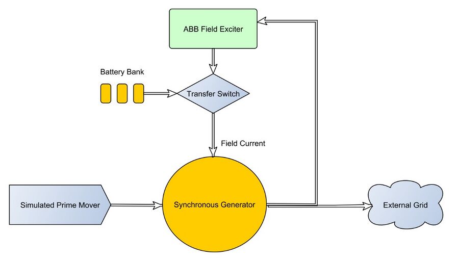
- Prime mover spins rotor to initiate a black start
- Battery bank provides excitation voltage and current directly to generator sufficient power is provided from synchronous generator to run the field exciter
- Black start system controls transfer of exciter power supply from batteries to generator power.
- Generator reaches rated output power.
- ABB field exciter controls excitation in steady state operation
Specs Table[edit | edit source]
| Specific Requirement | Description | Target | Acceptable Performance | Final Design |
|---|---|---|---|---|
| Size |
The Black Start System should |
36" x 48" x 36"" |
All dimensions |
6” x 12” x 18” |
| "Normal"
Operating Range |
Normal current through |
25 Amps DC and AC |
Can sustain 20 Amps or Better |
Switch does not carry full field current.
|
| Transfer Switch Control |
Controller determines when generator |
I/O ports capable of driving transfer switch command inputs. Communicate with exciter to |
I/O ports capable of driving transfer switch command inputs. |
Local Manual Control or |
| Forcing Output |
The transfer switch must be capable |
Up to 45 Amp AC or DC |
Sustain 45 Amp DC |
Switch does not carry full field current. |
| Exciter DC supply Voltage |
Battery bank voltage supplied |
24 VDC |
Min 18VDC Max 300 VDC |
Experimental data shows |
| Display |
The black start system should indicate |
Indicate power source |
Indicate power source |
Indicates black start active or battery charging |
System Design[edit | edit source]
System Circuit[edit | edit source]
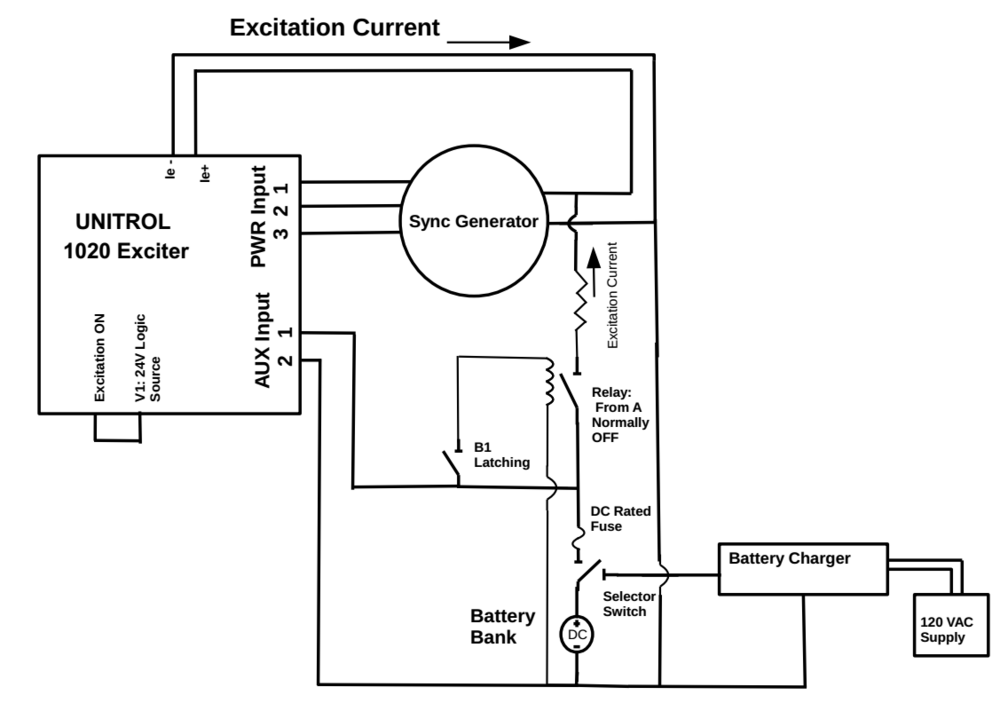
System Process: Local Control
1. Prime mover spins rotor to initiate a black start
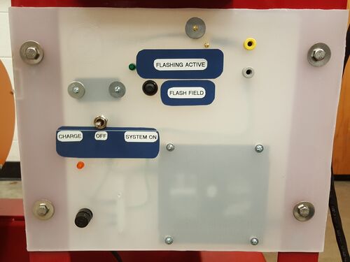
2. User turns selector switch to ON position to connect battery to black start system and power on ABB AUX power supply to AVR control system.
3. User presses momentary button 1 to turn relay on connecting batteries to field windings of generator.
4. Battery bank provides excitation current directly to generator. Sufficient power is provided from synchronous generator to run the ABB field exciter PWR inputs.
5. User releases button 2 disconnecting batteries from field.
6. UNITROL 1020 to starts its excitation current output in soft-start ramp up.
7. ABB field exciter controls excitation in steady state operation.
8. User turns selector switch to charge position to connect batteries to charger.
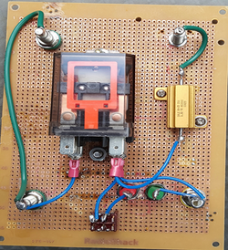
Design Prototype[edit | edit source]
| Front of Prototype Board | Front Connections |
|---|---|
|
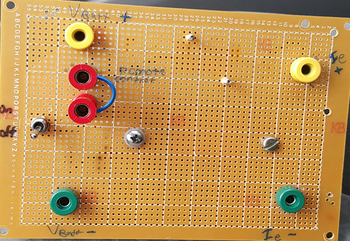
| Back of Prototype Board | Back Description |
|---|---|
|
Element details:
|
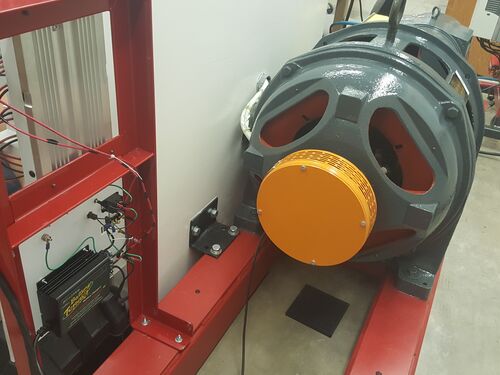
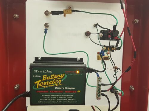
Final System Design[edit | edit source]
|
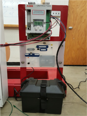
Front of Black-Start board |
|
|
No Excitation to System |
|
|
Attempt to Start Generator With AVR |
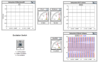
RTDS[edit | edit source]
|
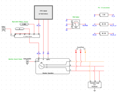
RTDS Complete System Model
|
|
|
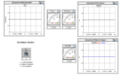
No Excitation to System
|
|
|
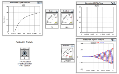
Battery Excitation
|
|
|
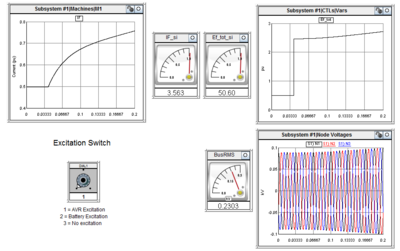
Switch from Battery to AVR Excitation
|
|
|
Steady-State Operation
|
Project Learning[edit | edit source]
ABB AVR[edit | edit source]
Planned Tests for Exciter System[edit | edit source]
1. Check that DCH Supervision Alarm works
Attach UNITROL PRW and Generator monitor inputs to autotransfromer output from lab voltage supply.
Connect UNITROL field output to dummy RL load simulating motor field windings
Increase voltage out of autotransformer to simulate generator output ramping up as field current builds.
Verify that DCH Supervision Alarm bit toggles at expected setpoint
2. Test field Excitation with 24 VDC source
Run generator with VFD controlled motor
Apply 24VDC from power lab DC power supply to field winding circuit to simulate the proposed battery bank. Use power supply current limit to prevent excessive current then remove current limit and test power resistors in series with source to limit current.
Observe generator output voltage rise time and final value with 24VDC excitation.
Team Information[edit | edit source]
| Team "Flash" | |||||
|---|---|---|---|---|---|
| Picture | Biography | Discipline | |||
| Will Parker | Will is a senior in electrical engineering from Palouse, Washington. He will be pursuing a masters in electrical engineering at the University of Idaho after graduation. His emphasis has been in power systems and power electronics. When not studying, Will enjoys backpacking, fly fishing, and gardening. | Electrical Engineering | |||
| Bruno Loza | Bruno is a senior studying electrical engineering with an emphasis in power. He was raised in southern Idaho and his hobbies include playing guitar, ultimate Frisbee, and soccer. | Electrical Engineering | |||
| Khalid Alotaibi | Khalid is an International student who came from Saudi Arabia. He is a senior in electrical engineering and his emphasis is power. In addition, Khalid loves to play and watch soccer. Other hobbies include volleyball, traveling, horse riding and swimming. | Electrical Engineering | |||
Documents Archive[edit | edit source]
System Specifications[edit | edit source]
File:2015 FieldFlash SystemSpecifications.pdf
Guides[edit | edit source]
File:2015 FieldFlash QuickStartGuide.pdf
File:2015 FieldFlash RTDSguide.pdf
Technical Presentation[edit | edit source]
File:2015 FieldFlash TechPres.pdf
