Goat stanchions for commercial milking
| [[File:|300px|center|alt=]] | |
| Sponsors | Peterson Metal Products, LLC |
| Team Name | Billy Goats Gruff |
| Duration | Summer 2019 - Fall 2019 |
| Faculty Adviser |
|
| Mentor |
|
| Client |
|
| Team Members |
|
The goal of the project is to produce a well engineered design for commercial grade goat milking stanchions. The design will then be produced in the form of a well documented engineering drawing package with manufacturing and installation instructions for the convenience of client and their customers.
Problem Definition[edit | edit source]
Background[edit | edit source]
Dairy goat farming is one of the fastest growing agricultural movements in the United States. Dairy goat herds have risen by %61 percent over the last decade. However, with the rise in popularity there is a problem for U.S based farmers. There currently is limited commercial grade milk stanchion manufactures in the United States and these products being produced are either single goat stanchions or high numbered stanchion systems. This is fine for huge scale operations or the hobby farmer but there is currently no option for the farmer looking to grow their business. For this reason many American dairy goat farmers have been forced to acquire their farming equipment either from Canada or European and Middle Eastern countries. Having local customer needs along with the growing popularity of dairy goat farming, our client desires to be able to produces commercial grade goat milking stanchions that will be suitable for a wide variety of farming types.
Deliverables[edit | edit source]
Specifications[edit | edit source]
Early Design Considerations[edit | edit source]
| Image | Description |
|---|---|
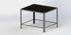
| Angle iron frame with HDPE insert for stand floor and bolt on bracing at the bottom. | |
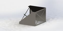
| Sheet metal stand with section view showing weld on supports underneath. | |
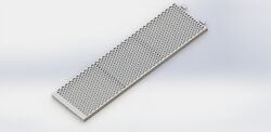
| Expanded metal ramp with hinge attachment to self level ramp with ground. | |
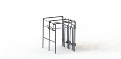
| Feed gate system with manual lever and gravity rotating feed boxes to avoid spilling leftover feed. | |
| Recommended system for Design Review 1. Expanded metal entry ramp. Sheet metal base and exit ramp. HDPE stall dividers and gate doors. | |
| Recommended system in use with additional two modules attached. |
2nd Design Iteration[edit | edit source]
| Image | Description |
|---|---|
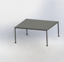
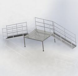
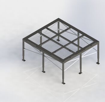
| Square tubing base with adjustable legs, expanded metal flooring and foot brackets to bolt to flooring or stake into the ground. The stand was expanded to have an additional loading and exiting area incorporated into the platform. | |
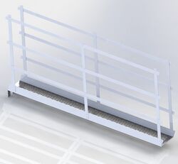
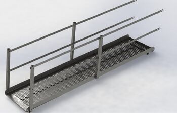
| Ramps made from expanded metal and bent sheet metal with tab and pocket connection allowing multiple ramps to be placed at varying positions around the stand. | |
| Example of entrance and exit ramp attached to pockets on opposite sides of the base stand. | |
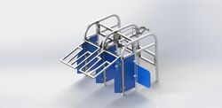
| Updated feed gate and stalls allows goats of varying sizes to enter feeding area with angled head restraints. Manual and automated lift system possible with addition of linear actuator to the gate lift bracket. HDPE stall doors and dividers keep goats from interacting during milking process. | |
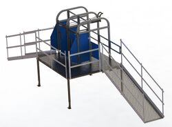
| Current system as of Snapshot 2. | |
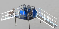
| Current system showing goat interaction. |
Project Learning[edit | edit source]
After being assigned this project the team’s first goal was to become more familiar with dairy goats and dairy goat farming. Dairy goat farming is one of the fastest growing agricultural movements in the United States. Herds grew by 61% between 2007 and 2017 according to the Washington Post. The major difference with dairy goats from other dairy animals is their wide range of sizes. Ranging anywhere from 20-35 inches tall and between 80-140 lbs. This makes farming equipment more difficult as it needs to be adjustable to accommodate many different sizes. The majority of our questions were answer from a group trip down to Leadore, Idaho to meet with our client. After arriving in Leadore we were able to tour the Peterson Metal Products shop to get an inventory list of their machines and what manufacturing processes we could use in the stanchion design. From there we traveled up to Salmon, Idaho to meet with Randal and Carol Stoker, a dairy sheep farmer in the area and owners of Mountain Valley Farmstead. On the farmstead we got to observe a homemade stanchion design Randal had developed in order to milk his sheep. Tour of Mountain Valley Farmstead Sheep Dairy Farm: Milking Parlor: The milking parlor was in a barn and consisted of a 3 ft deep concrete pit with rows of stanchions on each side. The stanchions were constructed from steel pipe which was bolted to the concrete floor. The stanchions had a railed walkway leading to four pens. Holding Pens: Each pen was equipped with a wooden door covering its entrance and a feeding trough blocking the end. The doors overlapped one another so they could only be opened sequentially beginning with the furthest door. Feeding Troughs: Above the feeding troughs hung flexible tubes attached to feed dispensers. The dispensers were filled by a large pipe with an auger supplying feed from a grain bin located in the loft above the milking parlor. The feed troughs were mounted to a gate which could swing upward to release the sheep after milking. Design Considerations Based on Observations: Stand: Most customers are unlikely to have a pit to use for stanchions sitting at ground level; however, stands and ramps could easily be sold separately. This would allow customers to more easily adapt the system to fit their existing facilities. Feeding system: Manually filling feed troughs before each milking could be a major inconvenience for farmers working with a large herd of goats. An automatic feed dispensing system could be a desirable feature for many farmers. Many customers may not have a loft to place their feed storage above their milking parlor so we will consider alternative feeding mechanisms. Dividers: The farmer had problems with goats stealing food from one another. We will solve this problem by including dividers between feed troughs. Doors: The overlapping door system which is used in nearly all commercial milking stanchions is a simple and efficient way to ensure all pens are filled. Material Selection Initially, we recommended aluminum for the primary construction material, but after further consideration and a meeting with our client, we chose steel instead for our final design. There were three main factors that influenced our decision: Cost-It costs our client roughly $2.50/lb (including material costs) to manufacture their products. Our client also confirmed this cost estimate held true for aluminum. Aluminum is far less dense and has a slightly higher strength to weight ratio than steel. Aluminum construction could be lighter than steel and thus cheaper. In practice however, the weight savings would only save our client a few hundred dollars per unit. Additionally, since our client primarily works with steel, it is likely they will save by drawing from the steel inventory and suppliers they already have set up. Manufacturing -While there are no significant differences in manufacturing costs between steel and aluminum, there would be increased setup time and logistical costs associated with alternating between steel and aluminum products. One advantage of aluminum would have been the ability for customers to attach brackets using self-tapping screws meaning fewer holes would need to be drilled during manufacturing. We were however able to reduce the number of required holes in our design to alleviate this problem to some extent. Durability -There is no significant strength advantage to either material; however, aluminum is significantly more ductile and softer than steel. This means steel would be more resistant to denting, bending and scratching. Steel is also more resistant to fatigue meaning that moving parts which undergo frequent load cycling may last longer if made from steel. Aluminum has superior corrosion resistance; however, since our client will be using a thermoplastic powder coating on most exposed surfaces, corrosion is not a significant concern. Construction: Bending Square Tubing- One of the first concept designs we presented our client involved square tubing with 90° bends. We recommended cutting 45° angles in the tubing and welding to form corners instead of using bends. Surprisingly, our client preferred bent tubing as it is more aesthetically pleasing and makes the design more difficult to copy. Bending square tubing with a 6-inch radius is not a major inconvenience for PMP. Deep Sheet Metal Bends- some of the sheet metal parts in our design called for deep and narrow U-shaped bends. After consultation with project mentors, it was decided to avoid such bends. There must be enough room for a V-die to make the bend. One exception was made for the brackets used to secure the frame legs to the floor. PMP has said they will make a custom die for the part. Tolerances -For ease of manufacturing, we have chosen a minimum tolerance for all parts of 1/8”. This will make construction faster and reduce the risk of parts not fitting. Expanded Metal Flooring -We initially recommended sheet metal flooring for the stand. After receiving feedback, we have switched to expanded metal which would allow for easier cleaning. Drawing Package There has been quite a bit of project learning while I have been creating the drawings, in addition to becoming reacquainted with the functions and features of Solidwork’s drawings. Most of my learning has been with editing the tables and table fillers on the page. Additionally, the cutaway image seen on Figure 20 was another learning point on using the “Broken out Section” feature on the drawing. This took some learning as I was playing around with the feature to get a clearer visual of the Item Number 6 for the BOM placed at the top left of the drawing. I went ahead and selected both square tubing parts underneath the expanded metal to not be damaged, and then typed in cut depths until the expanded metal was cut away from the area I had selected to view the parts I was enhancing. While I was remaking my drawing package, I learned that the sheet metal flat patterns can be displayed with a top and bottom visual. The largest difference here is that if a bend is to be made “downwards”, a dashed line is indicated along the bend. But, if a bend is to be made by folding a piece “up”, the line is indicated with a solid line. This creates a bit of difficulty, because I believe Dr. Swenson would like to see a dashed line for bends regardless of the folding orientation, so I may need to continue looking into manipulating some of the default settings to display a dashed line for everything on the drawing package (I have emailed him and am currently waiting on a response). More learning may occur later on
Our drawing package delivery showed us a lot about both scheduling and the technical aspects of putting together a manufacturing document. Dr. Swenson having worked in different industry atmospheres was able to give great coaching on how our drawings should be formatted and delivered. Ultimately it narrows down to how we can make it easiest on the customer. Communication was probably the biggest factor in our drawing packages. Early on the team was not all on the same page so we had a confusing layout and different styles when we compiled the various sub-assemblies together. This lack of communication and an overestimate of our ability to deliver the drawings in such a short time led to us being late on our deliverables to our client. The biggest technical learning on the drawing package was consistency. We learned that it is super important to make sure all the drawings flow together when different authors are creating them. This meant that notes and callouts all had the same font, size, distinctions, and locations. The measurement labeling all needed to be the same system and design; and elements should be placed in the same place on all the drawings. Once we broke the communication barrier, and got everyone in the lab together, we were much more effective in editing our drawings and production a deliverable drawing package.
Final Design[edit | edit source]
| Image | Description |
|---|---|
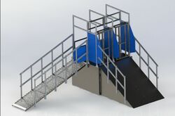
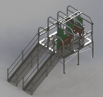
| Full system with base 2 stalls and additional stand and ramps. | |
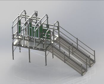
| Front view of full system. | |
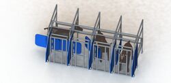
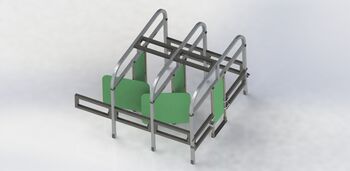
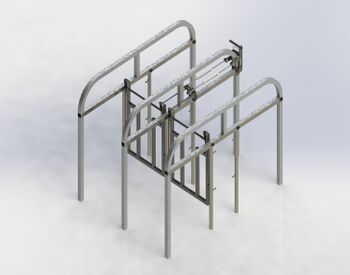
| This is the base stanchion system. Two stalls can be bolted to existing floor or staked down. Additional stalls can be added to either side to expand system. | |
| Additional stalls purchased can be placed on either side of the system via divider and clamps. Angle cut pipe hinge allows doors to be pushed open and gravity closed when goats exit. | |
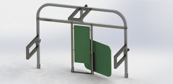
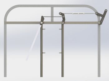
| Gates and lift system attached between two stalls. Square tube frame allows goats to eat while being held in place for milking. | |
| Side view-gate hinges at top with two linkages and handle. | |
| If desired, an adjustable stand may be purchased to raise the stalls. Stand constructed of expanded metal, sheet metal, and square tubing. | |
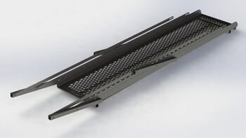
| Adjustable angle ramps constructed of expanded metal square tube and 10ga. sheet metal. Attachment tabs allow ramps to be located multiple places along the stand. | |
| Once the ramps are constructed they can easily be folded down to easy in shipping and installation. |
Prototyping[edit | edit source]
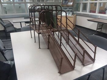
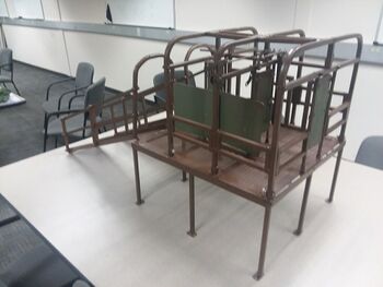
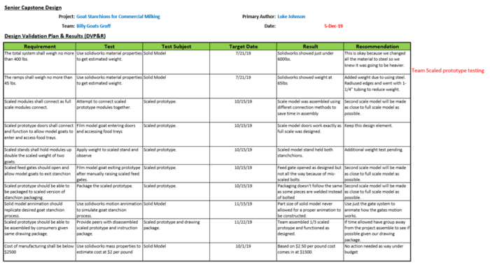
To analyze the manufacturing process and acquire design validation data a scaled prototype was made from the final drawing package. The prototype was scaled down to a 1/3 scale. Once the dxf files were scaled they were plasma cut on campus and the remainder of the materials scaled to 1/2 inch square tubing and expanded metal purchased in town. In an effort to complete the prototype in a timely manner some of the fixture methods were changed. many places that are bolted of clamped together in the full designed were welded together to secure the model. Once complete the prototype functions exactly as the full scale should. The doors open if pushed and close with gravity. The gates and hand lift function to raise the gates after milking. The ramps can move to different locations on the stand as designed. Lastly, the stalls can be removed from the stand as designed if the stand is not needed or ordered.
| Prototyping Images | Description |
|---|---|
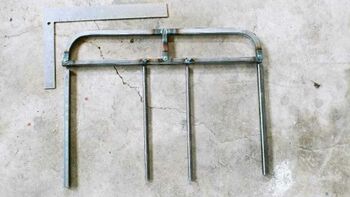
| Assemblies followed drawing package with parts scaled down by a factor of three | |
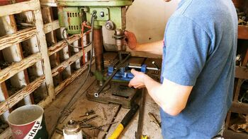
| Holes being drilled in the divider frame to hold gates. | |
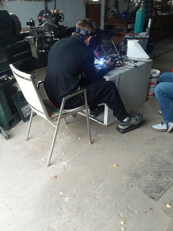
| Some areas were welded instead of bolts for time constraints. | |
| Full divider assembly welded and assembled before paint | |
| Full prototype with view of two ramp systems. | |
| Full view of scaled prototype. |
After completing the prototype we noticed a few design elements that needed changing. The stand was altered to remove a majority of the holes making it easier to manufacture and secure multiple stands together. It was also noticed that the front and back ramp slots needed adjusting to locate the ramp properly on these sides. Aside from these changes the prototype works exactly as the full scale was designed.
Manufacturing Fixture[edit | edit source]
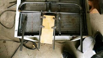
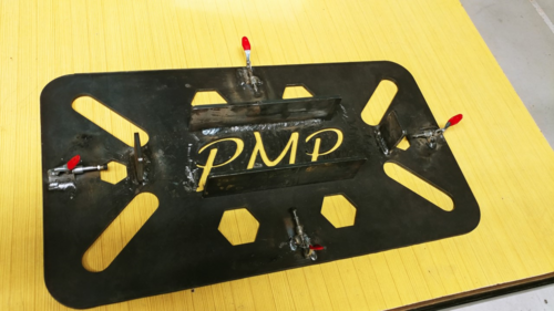
After the project drawing package was delivered and prototyping was completed, fixtures were designed to help the manufacturing of the numerous divider boxes. The fixture is made out of 1/4 steel so as the fixture gets years of use it will remain in tact and reliable. Tabs are placed in position to secure each side of the dividers in their proper orientation to one another. Push/Pull toggle clamps are placed on each side to secure sections to the location tabs.
Electronic Gate Lift[edit | edit source]
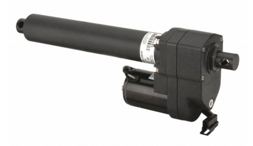
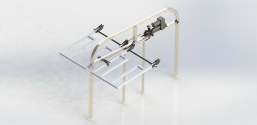
An addition to the manual designs was an incorporation of a linear actuator to autonomously raise and lower the feed gates. This required a re-design of one of the linkage brackets and an additional bracket that would secure the back mount of the linear actuator to the stall.The available actuator that operated with a four inch stroke had a rated load of 600lb, 60in/min (at rated load), aluminum gearing, weather resistant, and dimensionally fit within our existing frame design.
Validation[edit | edit source]
Team Members[edit | edit source]
|
Major: Mechanical Engineering
|
Major: Mechanical Engineering
| ||
|
Major: Mechanical Engineering |
Major: Mechanical Engineering
|
