Power Lab Motor Design and Experiment
| Sponsors | |
| Team Name | Pursuers |
| Duration | Spring 2019 - Fall 2019 |
| Faculty Adviser |
|
| Mentor |
|
| Client |
|
| Team Members |
|
The goal of the project is to create new lab experiments that help students in ECE 420 to get familiar with doubly fed induction machine.
Problem Definition[edit | edit source]
1.How to design a variable frequency power generation system? 2.How to use it to give power? 3.What machines do we need?
Background[edit | edit source]
In order to meet the needs of different experiments, power supply is provided in the electric power laboratory. After rectifying and inverting the original power, the voltage and frequency are more stable than the traditional power generation system, the output waveform is clean, the harmonic content is less, and the speed is insensitive.
Deliverables[edit | edit source]
So far, the project has been completed. Two experiments were designed to help students understand and use DC machine and double fed induction machine. In the next few columns, you'll see the results and the "snapshots" and "presentation" for these two semesters.
Instructions[edit | edit source]
DFIG
It is a wound type induction generator. A line-wound induction generator directly connected to a fixed-frequency three-phase grid by the stator windings. It can control the reactive power and decouple the active power and reactive power control by independently controlling the rotor excitation current. Doubly-fed induction generators are not excited from the grid, but from the rotor circuit. It can also generate reactive power, which can be transmitted to the stator via the grid-side converter.
DFIG consists of stator and rotor. The follow is an introduction of stator and rotor.
                                                                                Stator
 The stator is the stationary part of the machine. The stator is composed of stator core, stator winding and frame. The stator's main function is to generate a rotating magnetic field. The stator is composed of a frame, a stator core, a coil, and other structures that hold these parts in place. The stator core is the main magnetic circuit of the stator and is also the mounting and fixing part of the stator winding.
                                                                                Rotor
 A rotor is a rotating body supported by a bearing. When it runs, centrifugal inertial force will be generated, and affect the strength and mechanical efficiency of the rotor. The rotor is properly balanced. Redistributing the mass of its parts to reduce the centrifugal inertia force generated during rotation.
This is the picture for DFIG. The left side is stator. The right side is rotor.
Test Table
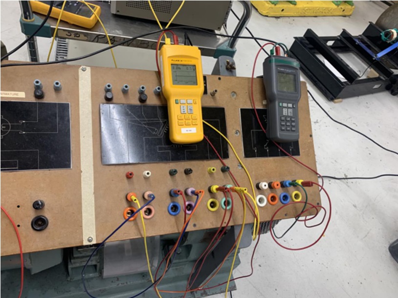
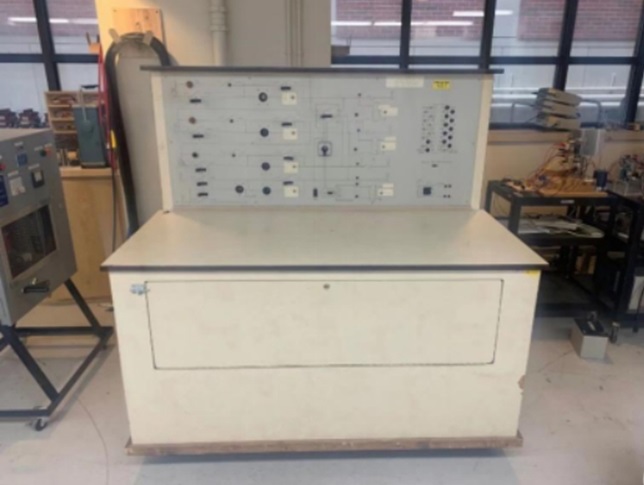
This is a table to measure the value. It covers voltage, current, and power. People can use it to measure the line voltage and phase voltage then verify whether the number is correct. Current also can use this way to verify.
Load bank
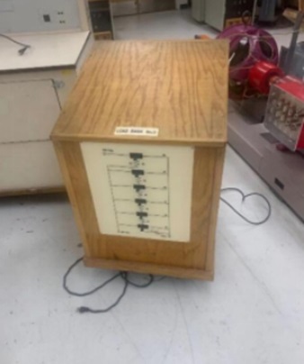
It is the resistance bank. People can add it to the experiment then change the value of resistance. It covers one phase load bank and three phase load bank in the power lab laboratory.
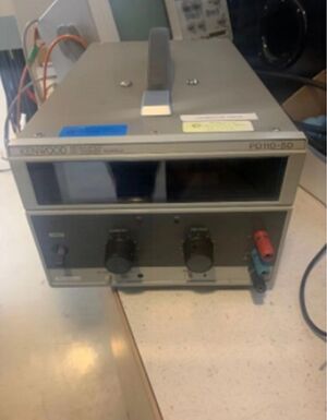
Power supply
Power supply can provide the voltage to the machine. When connect it to the machine. People can change the current or voltage in power supply than change the speed of machine( The first experiment will introduce more about this).
Project Learning[edit | edit source]
Knowing the function of different machines so that we can use different machines to satisfy different circuit requirements.
Final Design[edit | edit source]
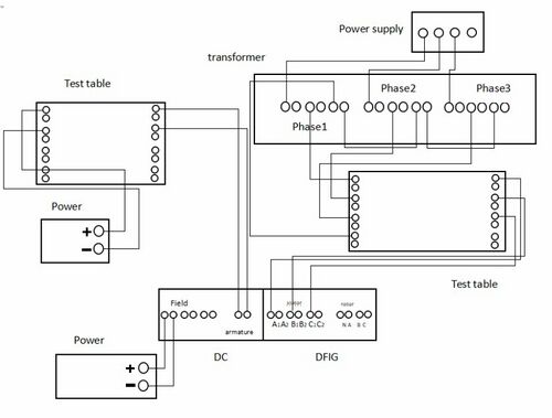
Experiment 1:DC Motor and Doubly Fed Induction Generator
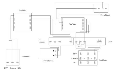
Experiment 2:DC Generator and Doubly Fed Induction Motor
Validation[edit | edit source]
Team Members[edit | edit source]
|
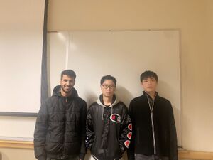
Name: Yuanchen Yan Major: Electric Engineering Hometown: China Responsibility: Leader Email:yan4963@vandals.uidaho.edu
|
Name: Almutairi Khalid Major: Electric Engineering Hometown:Saudi Arabia Responsibility:Budgeter Email: almu4958@vandals.uidaho.edu
| ||
|
Name: Jintong Zhang Major:Electric Engineering Hometown:China Responsibility:Create website Email: zhan1662@vandals.uidaho.edu
|
Additional Documentation[edit | edit source]
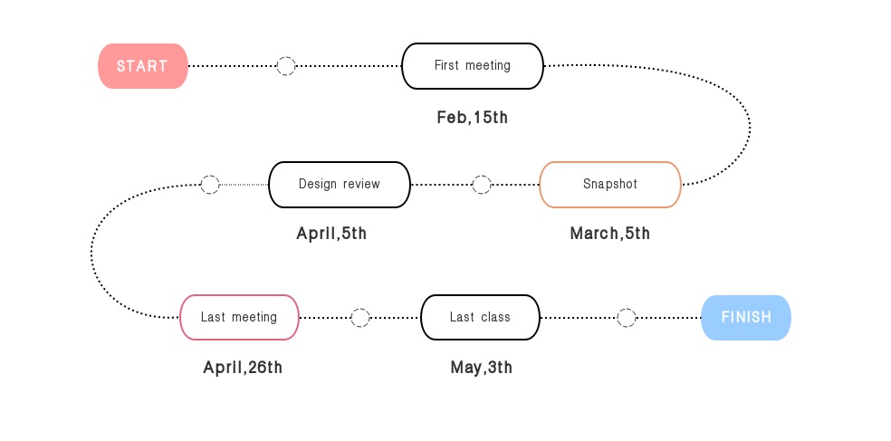
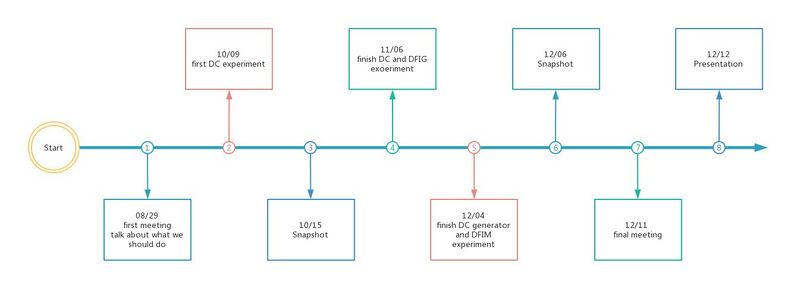
Timeline
Meeting Minutes
Snapshot
File:Snopshot.pdf
File:Snopshot2.pdf
File:Snopshot3.pdf
Desgins
File:Design.pdf
File:Design Final.pdf
Experiments
File:Synchronous machine.pdf
File:DFIG and DC machine.pdf
Lab Reports
