Sheet Metal Fatigue Fixture
| Sheet Metal Fatigue Prototype | |
| Sponsors | SEL |
| Team(s) | Get Bent, Beach Boys, Metal Bumblebees |
| Duration | Fall 2019 thru Spring 2021 |
| Faculty Adviser | Dr. Matthew Swenson
|
| Mentor |
|
| Client/Stakeholder | Schweitzer Engineering Labatories (SEL)
|
| Team Members |
|
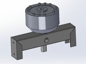
The project goal is to build and test a Sheet Metal Fatigue Fixture that can be used for cycling an aluminum sheet metal sample and produce a valid S-N curve (stress vs. number of cycles) describing its fatigue properties. In partnership with SEL, two senior design capstone teams, including an 8-week cohort, have developed a mechanical design and made progress towards a functional machine. With the design and components ready, the project is currently being physically built and tested by a third Senior Capstone Team.
Design Value Proposition[edit | edit source]
Background[edit | edit source]
SEL products are exposed to various cyclic stresses during their service life. These stresses are the result of thermal cycling, vibration, and direct loading. Sheetmetal, due to its non-isotropic grain structures, will have unique fatigue properties depending on part geometry. Hence, the S-N curves for specific sheetmetal materials are not commonly available. SEL products are rated for abnormally long life; therefore, it is important to know the S-N curves of given materials to predict the life of a product.
Fatigue testing requires multiple sample runs and each run takes a long time. To allow this, the fixture needs to be able to operate safely unattended. An ideal design will be optimized for quick setup, ease of use, cost of implementation, and repeatability.
2019-2020[edit | edit source]
Any metal will break if you pull or bending it hard enough. The more force you use, the faster it will break. If you use less force over and over again, it will take longer to wear out and break. An engineer needs to know this durability for materials after it has been bent or pulled many times. We know what this durability is for many metals, but things like heating and bending the metal can change its durability. Commercial machines to measure the durability of a material can cost between $10,000 and $300,000. Our goal is to build a low cost machine that can test pieces of sheet metal and tell us how durable it will be over time. This can be used to measure the strength of sheet metal after it has been worked (heat treated, finished, formed, ect.) or to verify the failure properties that are reported by a manufacturer.
Summer 2020[edit | edit source]
Limited data is available for characterizing fatigue properties of aluminum sheet metal materials, and its inherent non-isotropic grain structures make this characterization more difficult to accomplish. A new device to measure fatigue properties of sheet metal using a variety of sample geometries will enable advanced research to characterize aluminum materials.
A previous capstone design team (in collaboration with SEL) initiated the design of such a fixture, developing a strong foundation for a functional system. However, several key attributes of the system are not fully functional including:
- Crankshaft mechanism that cycles the samples
- Failure detection of a sample
- Speed calculations to determine the number of cycles
- Protective shielding
The goal of this team is to design a reliable way to:
- Cycle the sample
- Calibrate and use the load cell
- Programmatic detection of sample failure and frequency
- Build a prototype device
Our design will cycle an:
- Aluminum sample
- Detect loading and compute stresses
- Design and fabricate protective for safety and noise reduction
2020-2021[edit | edit source]
Sheet metals are utilized in a variety of applications and rolled sheet metal materials can have unique fatigue properties. Material properties of them are unavailable or hard to find, and solutions to find that data are highly expensive. The goal of the Sheet Metal Fatigue Fixture project is to build an affordable machine that will give reliable fatigue data on aluminum sheet metal. The machine will provide a reliable method to allow the user to understand the material properties of a specific piece of sheet metal at the end of the test. At the end of the project, a user will be able to enter varying sample sizes and select parameters. Then the machine will be able to run safely by itself, collect data and terminate automatically. The data will be used to find the stress versus number of specific cycles of a specific sample, provide fatigue data.
Deliverables[edit | edit source]
2019-2020[edit | edit source]
We have to deliver a final design fatigue fixture that can accomplish everything on the specifications list, but most importantly it most be able to create a S-N curve with very little human interaction.
Summer 2020[edit | edit source]
The eight-week cohort has made considerable progress in:
- Updated Mechanical Design
- Fabrication and manufacturing plans
- Shield design and fabrication
- Programming and hardware validation
- Documentation and Process Review
In the next sections, these system upgrades will be discussed.
2020-2021[edit | edit source]
By the end of October, the main assembly was fully built. Later on, the engineering problems such as vibration was addressed and the fixture was able to be run steadily with acceptable noise level. By the end of Spring semester, the program can successfully read total revolutions, speed and break detection feedback and connections with User Interface are set ready. The User Interface basic functions are also finalized and tested.
Specifications[edit | edit source]
The final product should have these considerations in mind:
- Handle up to 40 ksi of Static Stress.
- Overall Height, Width and Length shouldn't surpass 60 inches, 36 inches and 36 inches respectively.
- Can find an S-N curve of a sample at a minimum of 1 inch by 0.5 inches and a maximum of 6 inches by inches.
- Any material should be able to be tested, but specifically aluminum and plastic.
- Should be able to fit on a desktop.
- The fixture shouldn't surpass 70 pounds in weight.
- Eliminate all pinch points on the fixture.
- Setup Time for the fixture cannot exceed 45 minutes.
- User interface must be easy to view and interact with.
- Must be able to configure the operating force and frequency for a run.
- Must be able to run without continuous human interaction for a long period of time.
- The software must be able to generate an S-N curve using the results of the test runs.
- Control System must be able to detect when a failure occurs during the run.
- Operational noise cannot exceed 80 decibels.
- The frequency range that we must meet must be 1-100 Hz.
- Range of error cannot exceed 15%.
- Peak power load cannot exceed 1500W.
- Fixture must cost under $2,000.
- Fixture must be fully and partially reversible.
- Must be able to run from a wall socket.
Fall 2020 Project Development[edit | edit source]
Engineering Challenges[edit | edit source]
Mechanical challenges
• Whilst building the full assembly, the team has resolved some fit issues and made modifications to turnbuckle and shaft.
• The fasteners were upgraded to include prevailing torque.
• Deflection became noticeable once the fixture was powered on, which will need to be stabilized by adding a design solution to the current build to prevent this.
• While we were testing the motor, the fixture suffered intense vibration and had the potential to jump around. On that note, we needed to reduce vibration and set a minimal standard for this issue.
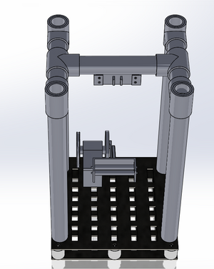
The fix to that problem we came up with is adding brace design to the fixture. After adding on that brace and testing before and after, the vibration was significantly reduced and the fixture was able to run steadily.
Fixture Design Modification
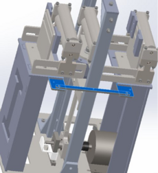
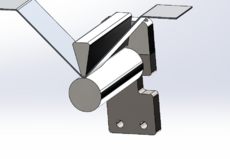
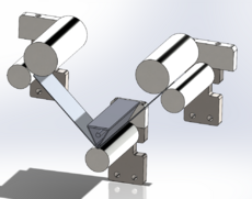
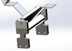
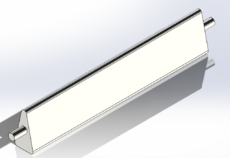
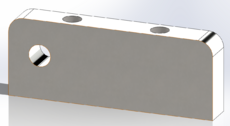
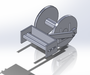
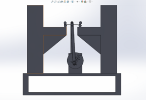
The team changed the top roller so that the fixture can accommodate 90-degree pieces of bent sheet metals.
For the modified bent roller design, there's a new cap allows for the sheet metal to be bent at 90-degrees.With the new cap, we need top rollers to keep the distance between the rollers the same.
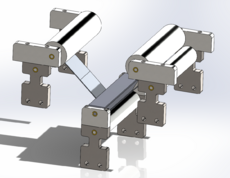
The pictures below show how the design will fit in the assembly.
For the modified here's a new center top roller to allow for the bent sheet metal to fit.
Hardware issues
We had to replace and upgrade some hardware components due to their functional issues. The Rasberry Pi refuses to connect from previous configuration. Considering the amount of time required to solve or reconfigure the old Rasberry Pi model, we decided to replace with a new model and import the software from scratch.
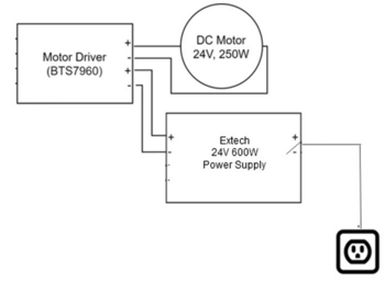
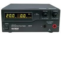
While testing the motor code, the old power supply broke down and eventually had a minor explosion. The motor drive is potentially shortcut as a result. After our consultation with EE professor Dr. Hess, we decided a more stable power supply with protection is needed, and we will replace with Extech DC power[1].. However, the Extech DC Power Supply isn't compatible with DC currents after a few tests. So, the team is currently working to select another functional and compatible power supply.
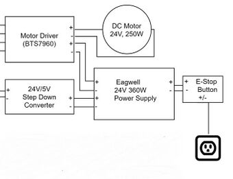
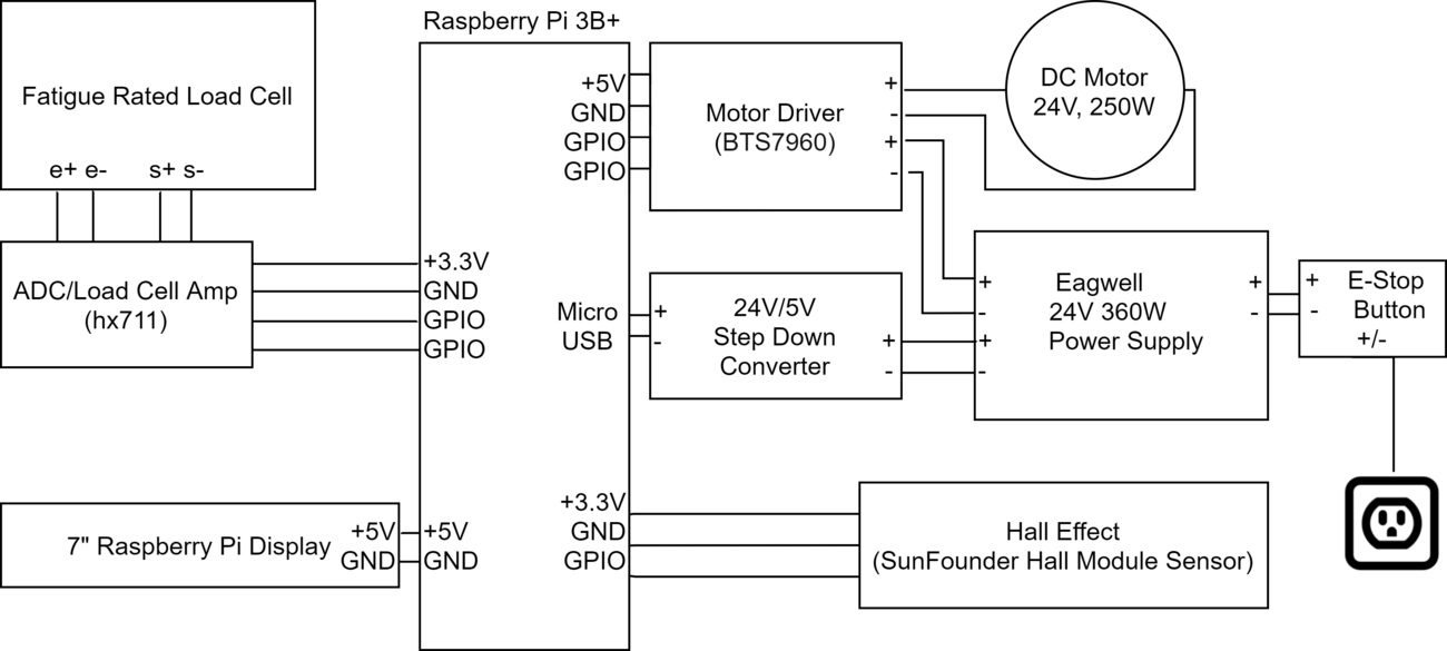
As a result, we redesigned our circuitry. The E-stop was removed owing to the built-in protection for the new power supply and Step-down Converter, which adjusts currents, was taken out too since we could now input the amperage, as you can compare the figures to the left and right. However, due to safety concerns and preferences for an emergency handler, we instead included a mechanical stop which ensures safety and allows us to save data if we shut down the system. .
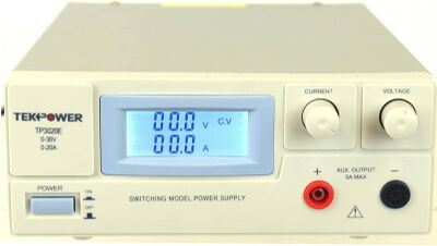
However, the Extech power supply wasn't compatible with the direct current system. The team is currently working on testing the functionality of a new power supply after several consultations with EE professor Dr. Hess. Having learnt from the failure of the previous Mouser, we have, after careful examinations of data sheets and application notes, confirmed that the protected new power supply, which is TekPower TP3020E, works with DC systems and fit the specifications of the motor. TekPower supplies 30V and 20A, for our project, we only need 80% of the max, allowing the fixture to run for prolonged time.
Besides compatibility, the other difference between Extech power supply and TekPower is that TekPower is unregulated, which means the output voltage could reflect the change in the input voltage. After continuous testing, TekPower has proved to suit our purpose and function well for prolonged periods of time.
Physical Development[edit | edit source]
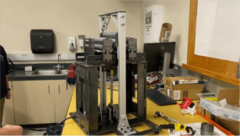
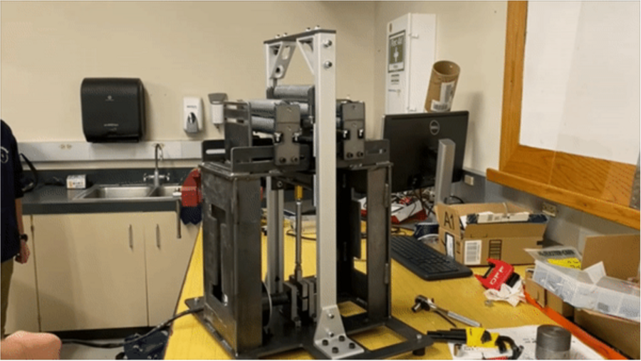
By the end of October, the fixture was fully assembled. With the main assembly built, we were able to test the fixture with the motor. The fixture was able to apply stress steadily without conspicuous vibration. By mid-March, the team was able to break acrylic and sheet metal samples using the fixture with acceptable noise level. We are also able to obtain total revolution and the speed of the motor while running the fixture.
Software Development[edit | edit source]
The software that controls the motor to start, speed up, slow down and stop is completed and functional. We have also completed scripts that manage the line sensor, load cell and break detection. The User Interface design and prototype are also finalized with connections to the system set up and tested.
The software class diagram below shows different classes that control different parts of device and serves as a blueprint for what a complete software system will look like.
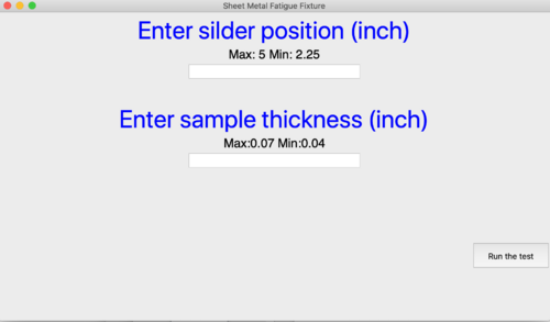
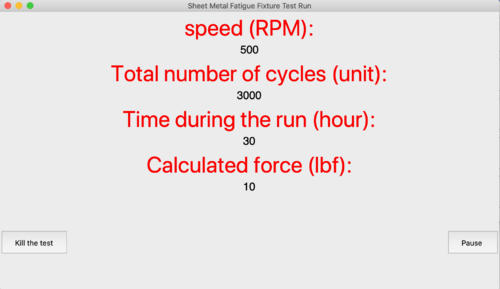
Below is the User Interface prototype. For the main page, if the user enters an invalid number, a warning message will be displayed. If the user enters no number in either blank, when the “Run the test” button is clicked, the program will give no response. Only if the user enters inputs within valid range, the program will run.Once the program starts running, the interface will direct us to another window that shows the process of the running test. Below shows an example of how the program monitors the test.
So far, we are designing the User Interface to function as an application on the Raspberry pi. Eventually, we will create an icon for the fixture test on the Raspberry Pi main page. When the user hits the icon, then the user interface program will start running. Thus, we don’t have an exit button on the interface.
Test Validations[edit | edit source]
Hall Effect Sensor
The team tested the Hall Effect Sensor with different magnetic fields while adjusting multiple test angles. The magnet field is only detected if fixed at a certain angel. The test was successful, however, the difficulty of being able to maintain an angel drove the team to find a more reliable sensor.
The team redid the test using an IR Break Beam Sensor and we are able to obtain the right speed from the readings. [2]
Break Detection
The team failed to detect break of sample because when the sample breaks there's not enough distance to detect current change. The team came up with multiple designs on the fixture to fix the problem, including adding tension to the ends of the sheet metals and drilling holes to fit wedges on the roller. Break detection will require further implementing.
Summer 2020 Design Considerations[edit | edit source]
The Summer 2020 team finalized the crankshaft mechanism and load cell actuator mount.
Crankshaft Mechanism[edit | edit source]
Useful S-N curves require a wide range of stress acting on the sheet metal samples. It was proposed that the ability for the user to change the deflection of the center roller would be the best method of altering the stresses in test samples.
Due to the high-frequency operation requirements (~40Hz), the crankshaft mechanism needed to be robust and produce consistent deflections throughout the testing period.
Careful consideration of the potential sample sizes proved that alteration of the sample (changing the active length and width of the sheet metal) would create a suitable data points for an S-N curve. The team decided that designing the crankshaft mechanism to produce one deflection would be the most practical considering cycle replication.
Eccentric Crankshaft Design[edit | edit source]
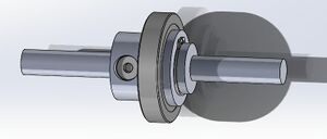
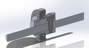
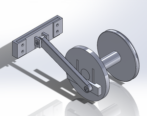
The team decided a deflection of 0.097in would create a range of stresses from 4500-40000 Psi generation of an S-N curve. This deflection is generated using an eccentric shaft. A larger off-set lobe is coupled to the main drive shaft, at a 0.097in offset center to center. This method replaces the previous teams' 3 point bending system.
Load Cell Actuator Mount[edit | edit source]
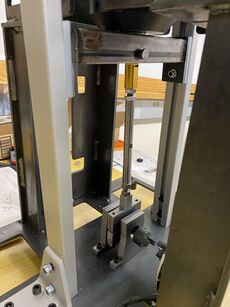
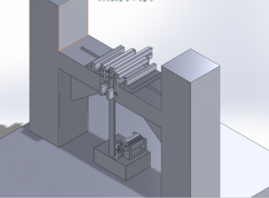
The 2019 design team incorporated two aluminum channels that serve to maintain a completely axial motion path for the load cell. The load cell is a sensitive instrument and small non-axial loads can significantly alter output data. The 2020 team redesigned the load cell mount to emphasize the purely axial loading requirement.
Fall 2019 Design Considerations[edit | edit source]
This section will go through the three design choices we went through; those being Axial, Cantilever and 3-point Bending.
Axial (Concept #1)[edit | edit source]
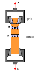
At first Axial sounded like the most obvious option to go with, however the more we looked into the requirements, the more Axial looked impossible to do.
Axial had the most simple design, but it also introduced a lot of issues. Axial has a lot of potential for buckling forces and that would prevent compressive loads, which we need in order to make the fixture fully reversible. Buckling forces also directly effect the amount of force needed to fracture not only the sample, but the fixture itself. The max force needed to fracture a 6"x6" aluminum sample would be 14400 lbs, which is unobtainable for what we're trying to do, so if we were going with Axial, the longest a sample could get is 1.72".
This showed us that Axial wasn't a good choice for this project.
Cantilever (Concept #2)=[edit | edit source]
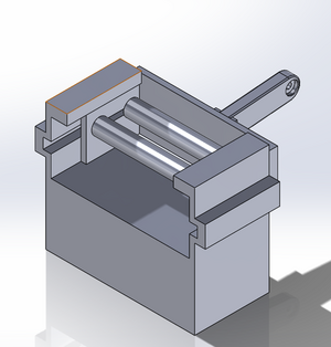
For the Cantilever Design the initial design was with round pipe supports and two base plates. The slots in the base plate were to reduce the weight of the machine. The round spacers between the plates are to model rubber shock absorbers. The tubing would be welded together. The initial design for the power train involves a pulley and a fully adjustable wheel linkage. The clamps are just plates to with bolts to sandwich the ends of the sample in place.
The second design for Cantilever is the same as the first just with some more updates to the clamping on the motor linkage end as we found that with two solid clamps we would over constrain our Free Body Diagram of our sample and create indeterminate loading. We solved this by adding roller clamps to the motor linkage instead of the positive clamping we originally considered.
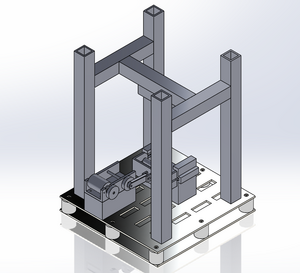
Our third design involved some major changes to the design. For starters we changed the round pipes out for square tubing and we modeled our motor and a new motor linkage setup. Further more we added a block for to to hold our linkage parts and change our loading from cyclical to pure bending.
The reason we did not pursue this design was the inconsistency in the failure point. In theory it should always be right at the bottom of the top clamp, but after talking with Dr. Bob Stephens a fatigue expert at the University of Idaho we learned that this was not always the case in reality. This would give us inaccurate results and would be outside our required accuracy.
3-point Bending (Concept #3)[edit | edit source]
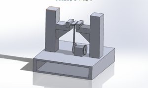
Our first 3-point design was a steel structure using rollers to apply points onto the specimen, the specimen was held down using two clamps on each end, the issue with this design was that this created two fixed end conditions which would not yield the correct shear moment diagram that we needed.
After some small changes we had our second design which held most of the same components with the biggest change having rollers hold down the end of the specimen which gave us the proper shear moment diagram to ensure that we would have the max moment at the center of the specimen. The issues with this design were that we were concerned that the sample would slide out of the rollers once the object began to vibrate.
Our third design and current design has an added L-bracket to ensure no movement in the horizontal direction, there are also added t-slots which will hold the L-brackets in place. We decided to go with this design because it was the simplest set up that would provide the results that we wanted.
Controls[edit | edit source]
The Control System is broken into 5 individual components:
Load Cell[edit | edit source]
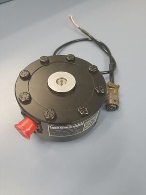
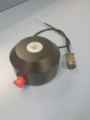
We need a load cell that is strong enough, so that it won't break after several million cycles. Many load cells are not built for this kind of repeated loading, so we're forced to look into fatigue-rated load cells. Fatigue-rated load cells are much more expensive; the load cell consists of 4 strain gauges in a Wheatstone bridge configuration. We apply an excitation voltage of up to 10 V and we get an output proportion to the applied load.
Our controller doesn't support reading an analog signal, so we need an analog-to-digital converter and an amplifier for the load cell. We went with a load cell amplifier powered by the HX711; this let's us read the output from the load cell at speeds up to 80 Hz. We are unsure of the accuracy we will get from this combination of load cell/ADC, since we are applying an excitation voltage of only 5V. Our output will be half of the rated voltage.
The load cell we decided to go with is the LPSW-B-300. The capacity for this particular load cell is 300 lbf, which is more than enough for what we need (max of 100 lbf). The load cell is made of aluminum, weighs 2.5 lbf with the base, is suitable for our room temperature testing environment, isn't fatigue-rated but is used for long cycles of testing and measures in both tension and compression.
Motor/Motor Driver[edit | edit source]
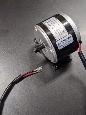
To stress our sample at the required load and speed, we will need a motor that is 250W. We found that electric scooter motors are exactly the power, speed and reliability we need with a duty cycle of 100%. The chosen motor is a 250W permanent magnet brushed DC motor, with a rated speed of 2650RPM (44Hz).
To drive the motor, we found a hobbyist motor driver on amazon that allows us to power the motor from a separate power supply as our controller can only provide 5V. The driver we chose is rated for up to 45A, and we will only be providing 14A.
Failure Detection[edit | edit source]
Our initial plan was to clamp positive and negative leads to each end of the sample in question. If the sample breaks, we can detect that there is a broken circuit and stop the test. However, that would require insulating every contact point of our fixture so that current can only flow through the sample. We decided this is infeasible. Instead we will monitor the load reported by our load cell. If our load is sufficiently low, we know that the sample broke and we should stop the test.
Tachometer[edit | edit source]
To measure the speed of the motor, we have a hall effect sensor mounted near the driveshaft of the motor. Attached to the driveshaft is a magnet. On every rotation of the shaft, we get a pulse from the hall effect sensor. This lets us measure the number of rotations, and by measuring time between pulses, we can measure the angular velocity of the motor. If our motor is moving slower than our desired speed, we can adjust it on the fly. This will be a simple proportional control system.
Raspberry Pi[edit | edit source]
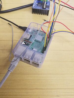
All the components of this system are connected to a Raspberry Pi 3B+. The control software is written in Blazor using ASP.NET in .NET Core 3.1. Since we aren’t using a real time controller like an Arduino for our control system, we need to avoid heavy software loads. C# allows us to write performant code in a way that is easy to build a UI and is not very platform specific. Unfortunately, there weren’t any libraries available to read data from the HX711 used in the load cell amplifier, so we build a small python program to read from the HX711 and send the data over a named pipe.
User Interface[edit | edit source]
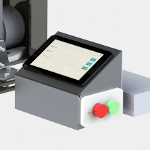
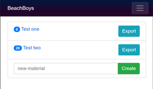
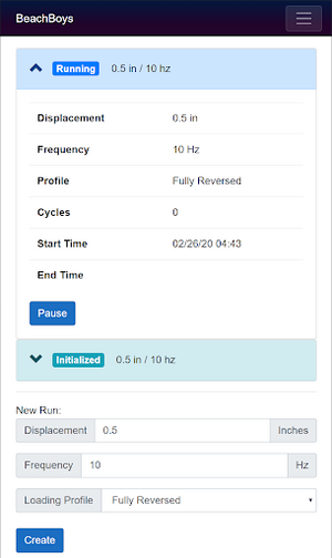
The user interface allows a user to control the fixture and store/export data about run experiments. The UI can be viewed via any web browser on the network, but an attached display makes it quick and easy to interact with. (Left photo)
The main view shows a list of different materials. From there a user can export an SN curve to an Excel spreadsheet. Each experiment stores a list of test runs. Each run stores information like the prescribed displacement, set frequency, loading profile (fully reversed, partially reversed), number of cycles, start time, and end time. This information is stored in non-volatile memory on the raspberry pi as a JSON file. (Middle photo)
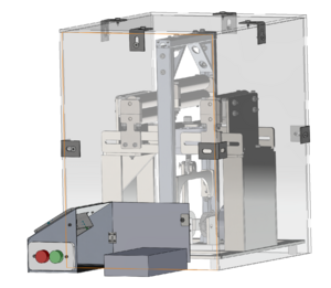
To hold all of the electronics, a small housing made of sheet metal holds all the components together separate from the main assembly. This keeps the components safe from any vibrations caused by our fixture. (Right photo)
Prototype[edit | edit source]
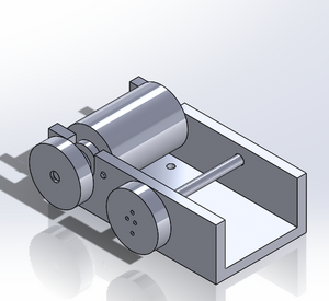
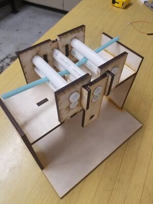
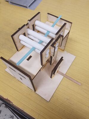
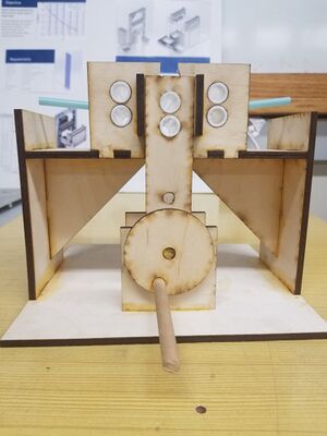
To help show physically and visually what our project is about, we created a prototype 3-bending fixture out of wood. The fixture itself was constructed by laser-cut wood and the rollers are just cut PVC pipe to fit the dimensions we needed. We didn't power the prototype fixture with a motor, like we will with the actual fixture, we instead used a hand crank so that we could quickly make the prototype, show how the fixture will function and so people could interact with it. Instead of a piece of sheet metal, we used a plastic straw as our sample, because a PVC pipe would not be able to bend metal.
Overall, this prototype was a success and it helped us better visualize our design. It was a great building block for the project.
Project Learning[edit | edit source]
2019-2020 Summary and Links[edit | edit source]
Decision Matrix's for the Fixture and Motor
Comparison of Failure Detection Methods
Motor Linkage Power Required Analysis
Cantilever Design Review Concept
Concept Review Design Recommendations
Spring 2020 Design Conclusions[edit | edit source]
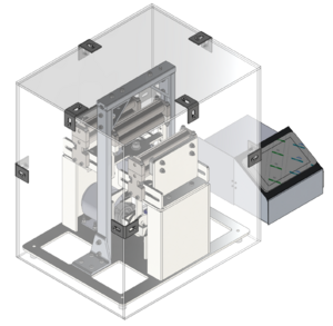
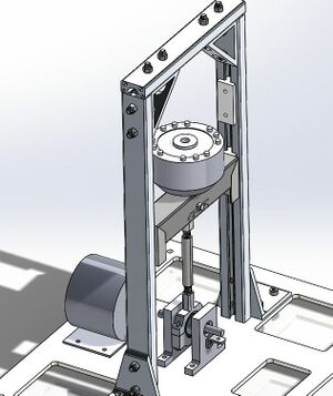
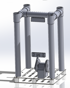
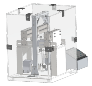
The final design utilizes a scooter motor and a load cell to provide and measure our force. The sample is mounted on between two rollers that are shim-able to account for differing sample thicknesses. The fixture is enclosed in a clear acrylic case that drops over top of the assembly. The electronics and the interface are outside of the acrylic case to help with cooling needs. The aluminum towers act in conjunction with some UHMW plastic sliders as linear glide blocks allowing the linkage to transmit a purely axial force to the load cell and then up into the sample. The rollers were updated from the very simplistic plastic model we had on our prototype to steel commercial rollers, but due to cost considerations we have opted to build our own steel rollers in house. The backstop will be made from 3-D printed plastic and its function is to stop the sample from vibrating out of the rollers. The rollers run on oil impregnated bronze sleeve bearings in order to reduce wear and these same bearings are used in the linkage as well. The rollers slide in and out to accommodate varying sample lengths and can take up to six inch wide samples as well.
Spring 2020 Project Construction[edit | edit source]
Due to the COVID-19 outbreak, the timeline and goal of our project was changed. We could no longer meet in person, couldn't use campus resources like the machine shop, senior capstone room, computer labs, etc. This really threw a wrench in everything that we had planned to do after spring break. Without these resources, we couldn't machine our design at all, so we had to take a step back and re look at our design. Instead of focusing on building and testing a fixture, we swapped to making our designs the best that they could be. This included making our sub-assemblies fully realized, designing new parts, making weldaments, finding the correct nuts and bolts, finishing our manufacturing plan and completing our drawing package. Our current final design is a lot more well thought out and fully realized than the one we had prior to spring break.
The final goal of our project was changed to creating a fully realized model, with a well put together manufacturing plan and drawing package, so that it's easy for the next group to put together the fixture and begin testing. We believe that we have met that requirement.
2019-2020 Future Recommendations[edit | edit source]
We recommend that this product be fully constructed either by another capstone team, over the summer by a grad student or by SEL. Testing and iteration will be needed to fix any issues we couldn’t foresee in the design phase. We would love to see this project be used for its intended purpose, to test the fatigue strength of aluminum samples for SEL and make an S-N curve. Finally we advise any future workers to create multiple configurations of the linkages to test varying sample thicknesses and shapes. The motor linkage system also needs to be reworked to a smoother design.
Summer 2020 Design Review[edit | edit source]
At the midpoint of the 8 week cohort, a comprehensive and detailed design review was given to members of SEL team, faculty and class peers. Below is a copy of the presentation presented.
Topics Covered:
- Discussion of fixed vs. variable deflection
- Implementation of design decisions
- Math Models
- Section Views of SMFF system
- Summer 2020 Design Changes
- Manufacturing Plan
2020-2021 Design Review[edit | edit source]
Fall2020 Design Review took place over Zoom on November 13th. Firstly, This presentation introduced the background, justified the need, and explained the objectives of the fixture. Then it gives a dissection of how the mechanism of the fixture in regards to mechanical engineering and computer science. With the progress made on both sides, some recommendations were made and potential risks were identified, which was presented along the development. The emphasized improvement on the fixture design is the brace design which reduces vibration and the changed circuitry for safety. Finally the presentation finishes up with project management filling in validation plans, following work schedule and budgetary management.
Fall2020 Design Review Presentation
Team Members 2019-2020[edit | edit source]
| Ryan Blair
Major: Mechanical Engineering Hometown: Kamiah, Idaho Responsibility: Fixture Design, Manufacturing and Co-Lead Designer Email: blai3845@vandals.uidaho.edu
|
Chase Croft
Major: Mechanical Engineering Hometown: Everett, Washington Responsibility: Team Leader, Wiki Master, Treasurer and Manufacturing Email: crof6743@vandals.uidaho.edu
| ||
| Anthony Kitchen
Major: Mechanical Engineering Hometown: Kellogg, Idaho Responsibility: Fixture Design, Manufacturing and Co-Lead Designer Email: kitc5657@vandals.uidaho.edu
|
Alex McNurlin
Major: Mechanical Engineering & Computer Science Hometown: Hansen, Idaho Responsibility: Control System and UI Design, Client Contact and Lead Analyst Email: mcnu5088@vandals.uidaho.edu
|
Team Members Summer 2020[edit | edit source]
| Jayden Hartley
Major: Mechanical Engineering Email: jayd4329@vandals.uidaho.edu
|
Omar Alghamdi
Major: Mechanical Engineering Email: algh1147@vandals.uidaho.edu
| ||
| Camille Eddy
Major: Mechanical Engineering Email: eddy0292@vandals.uidaho.edu |
[[File:|180px|thumb|left]] |
Elliot Marsden
Major: Mechanical Engineering Email: mars2123@vandals.uidaho.edu
|
Team Members 2020-2021[edit | edit source]
| Siobhan McGuire
Major: Mechanical Engineering Email: mcgu1014@vandals.uidaho.edu
|
Tyson Otsberg
Major: Mechanical Engineering Email: obst6823@vandals.uidaho.edu
| ||
| Jorge Gonzalez (Fall2020)
Major: Mechanical Engineering Email: gonz6108@vandals.uidaho.edu |
Yingruo Liu
Major: Computer Science Email: liu6033@vandals.uidaho.edu
| ||
| Dylan Card
Major: Computer Science Email: card0899@vandals.uidaho.edu
|
2019-2020 Additional Information[edit | edit source]
Beach Boys Project Schedule
Beach Boys Meeting Minutes
Beach Boys Manufacturing Plan
Beach Boys Presentations
Engineering Release Review Presentation
Beach Boys Client Interview
Beach Boys Budget
Summer 2020 Validation, Budget & Schedule[edit | edit source]
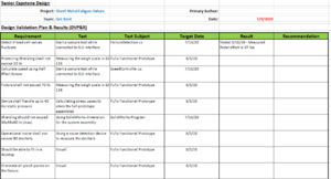
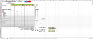
The Design Validation Plan states requirements and the basic plan of testing should proceed at a future date. The project budget and schedule have been updated for Summer 2020
2020-2021 Additional Information[edit | edit source]
Metal Bumblebees Climate Interview
Metal Bumblebees EE Professor Meeting
Metal Bumblebees Design Validation Plan
Metal Bumblebees Engineering Release Review
Metal Bumblebees Concept Development Review
Metal Bumblebees Technical Presentation
Metal Bumblebees Schedule
Metal Bumblebees Budget
Metal Bumblebees Inventory
Metal Bumblebees Meeting Minutes
Metal Bumblebees Snapshot
