TAPS: Touch-Based Adaptive Predictive Screen
The main goal of this project is to produce a touchscreen product that adapts dynamically to changes in light intensity and vibration in order to provide an excellent user experience. The product developed will be able to work effectively under a wide range of light intensities as well as under different kinds of physical vibration (both rhythmic and non-rhythmic) in all directions. The process of developing the product will also involve the design of experiments to adequately test its functionality. The designed experiments will be conducted and the results obtained and analyzed. In the future, the evolutionary process might involve adding functionality to compensate for the contamination of the touchscreen surface.
| TAPS: Touch-based Adaptive/Predictive Screen | |
| Sponsor: | Esterline |
| Duration: | Fall 2014 - Spring 2015 |
| Faculty Advisor: | Professor Feng Li |
| Mentors: | |
| Team Members: | |
Problem Definition
Background Many touchscreen products are unable to adapt adequately to dynamic environmental changes, such as changes in light intensity and the introduction of vibration. These environmental factors introduce errors such as “false touches,” which result in the trigger of unintended screen functionality.
Deliverables
- The touchscreen system should compensate for environmental vibration incidences
- The touchscreen system should compensate for environmental changes in light intensity
- The design should incorporate a means of switching the compensation on or off
- Experiments should be designed and conducted to test system functionality
- The system should compensate for user finger jitter
Specifications The specifications table is below:
| Metrics | Units | Unit Alias | Marginally Acceptable | Ideal |
|---|---|---|---|---|
| Percentage of false touches | Number of false touches per 1,000 touches | FTT | 20% decrease with compensation | 80% decrease with compensation |
| Discernibility of On-screen Characters | Number of discernible characters per page | CPP | 50% increase in CPP with compensation | 90% increase with compensation |
| Response Time | Microseconds | μs | Maintains at most the current response time | Reduces the current response time |
| Accuracy | Millimeters | mm | 20% increase in CPP with compensation | 50% increase with compensation |
| Aesthetically pleasing | Subjective | N/A | Presentable | Very aesthetically pleasing and trendy |
| Cost of product prototype | Dollars | $ | Within budget | Within budget |
| System stability with and without peripherals | Binary | N/A | Yes | Yes: with all peripherals |
| Number of interfaces | Interfaces | Int | USB | USB |
| System Controller | Hardware Model | N/A | Any capable processor | ARM Cortex A8 |
| Togglable Compensation | Binary | N/A | Yes | Yes |
Project Learning
Vibration Compensation
The touchscreen product must be able to appropriately respond and make compensation to inputs received in an environment with vibrations. There are two primary forms of vibration incidents that this project considers: rhythmic vibration and random vibration. Rhythmic vibration is prioritized over random vibration for this design, because rhythmic vibration is more common.
Rhythmic vibration is a vibration incident that remains relatively the same in magnitude throughout the incident and occurs in a predictable, repeating pattern. An example of rhythmic vibration would be the vibration experienced by a massage chair, or the vibrations felt when driving down an evenly-paved, flat road.
Random vibration is a vibration incident that does not necessarily have the same magnitude throughout the incident and is unpredictable. An example of random vibration would be the vibration experienced by brief, unexpected turbulence by an aircraft, or the quick jolt of accidentally driving over a pothole.
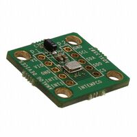
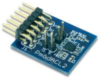
Effects of Vibration Both types of vibration incidents will cause the screen to move to some degree and cause more difficulty for the user to touch the desired section of the screen. This effect will most likely cause additional false touches. One way to help characterize the incoming vibration is to use the appropriate accelerometer. For this project, two simple silicon-based accelerometers were selected, the ADXL350 and the Digilent PmodACL2.
Accelerometers
|
|
|
| ADXL350 Accelerometer | Digilent PmodACL2 Accelerometer | BMA180 Accelerometer |
The ADXL350 accelerometer was considered for the project initially because it has SPI and I²C inputs and outputs, making the ADXL350 compatible with most microcontrollers. Another primary deciding factor for consiering the ADXL350 was that it can measure ±1 to 2gs, which is the expected necessary range for the project. Additionally, the ADXL350 is very customizable, as it lets the user specify the acceleration range (from 1 to 8gs) and the bandwidth (from 3.125Hz to 1.6kHz). The ADXL350 also records data from measurements in the x, y, and z directions. For information, refer to the ADXL350 datasheet[1].
The Digilent PmodACL2 accelerometer was considered in addition to the ADXL350 accelerometer because it may be easier to work with as more documentation for the PmodACL2 exist. Interfacing with the PmodACL2 is done through SPI, which makes the PmodACL2 very user friendly when working with microcontrollers and similar devices. The PmodACL2 features selectable ±2, 4, and 8 g measurement ranges with anti aliasing protection for measurements taken. The PmodACL2 is also capable of taking and recording measurements in three dimensions[2]. For more information, please visit the PmodACL2 reference manual[2] and the PmodACL2 schematic[3].
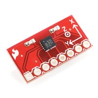
The BMA180 Accelerometer was selected as the accelerometer of choice. It is a triaxial ultra high performance digital accelerometer with switchable g-ranges and bandwidths. It has both I2C and SPI 4-wire interfaces with an interrupt pin. It has several programmable features: g-range, integrated digital features, interrupt features, power modes and some enhanced features. The customer programmable g-ranges include 1g,1.5g,2g,3g,4g,8g, and 16g. BMA180 Datasheet[4]
Lighting Compensation
The touchscreen must adapt its user interface to compensate for the varying levels in surrounding light. The surrounding light is most commonly referred to as ambient light. The screen should attempt to compensate, dynamically, to the surrounding light levels. Most ambient light sensors use photodiodes or photoresistors to relate the light intensity.
Photodiodes are based on the physics of semiconductors. They are devices which convert light into current. When light intensity increases, the amount of current produced increases.
Photoresistors is a resistor that changes with light intensity. As light intensity increases, the resistance of the photoresistor decreases.
Light Sensors BH1750 is a light sensor that has a wide range and high resolution. It has an I2C interface for the output. This light sensor was chosen for its ease of use as well as it high resolution. Because its output is digital in I2C format, the sensor will be easy to integrate with existing controllers. The light sensor also has a wide operating range for temperatures. For more information, please visit BH1750 reference manual[5].
Project Timeline
This is the Project Timeline that will guide the development process. It includes project deadlines and phases.
Design Solutions
The section includes design solutions for both light and vibration compensation.
Light Compensation Solutions
There are two solutions that are being developed for adaptability to light intensity. The first solution, the segmented line method, uses the equation of a line to generate contrast (RGB) values in between a range set by the experimentally determined best contrast values at a given light intensity. The experimentally determined values are obtained by a sample of individuals who give their opinions on what the most visible iteration is. The light intensity values at these points can be read from the light sensor. The experimentally determined values are stored in a look-up table in code so the line equation at a given range can use the proper bounds. The second solution, the segmented curve method, was developed in the event that the segmented line method uses too much memory and/or is too slow. The segmented curve method uses the same means of obtaining the experimentally determined values, but instead of these values being stored in a look-up table they are put into a spreadsheet program and analyzed with a curve fit line. The equation of the curve fit line may be segmented into ranges if the total equation is too complicated.
For the light solution, one TSL2591 light sensors will be used. The Beagle Bone Black (BBB) has two I2C interfaces: I2C0 and I2C1. The light sensor will be connected, with the accelerometer, to I2C0. Below is a diagram of the physical placement of the light sensors.
Vibration Compensation Solutions
There are two solutions that were considered for vibration compensation. There are two kinds of vibration that are expected to be experienced: rhythmic and pulse vibration. Also, compensation will only be done for vibration encountered in the x and y axes. Below is a general control flow for how vibration compensation will take place. The system will utilize the Steady State Screen solution.
Proportional Magnification This solution attempts to emulate what is observed when a magnifying lens is used. It involves magnifying portions of the screen in order to make the screen display components easier to see and access. The system determines what portion of the screen to modify based on input from a proximity sensor. The proximity sensor provides information about what area of the screen the user is closet to and how well. After much consideration, this solution has been put off since the alternative solution has been found to me more efficient in solving the problem.
Steady State Screen This solution involves shrinking screen display components and shifting the screen display in order to counter vibration effects. This approach does not employ a proximity sensor, but has a limit to the amplitude of vibration that can be tolerated. This is because the screen display shrinkage depends on the amplitude of vibration being experienced and it would be unreasonable to shrink the screen display beyond a certain limit. However, this solution is better for pulse vibrations and is less intrusive to the user. This solution has been selected as the main adaptive response to be implemented.
Testing
In this section, the method of obtaining data for algorithm development as well as the data observed from tests will be discussed.
Vibration Testing
The methods used for collecting test vibration data were dual faceted. The first method used was a vibration plate. The accelerometer and the Beagle Bone Black were placed on top of a vibration plate that created rhythmic vibrations. The second method utilized to collect data was captured by driving down a gravel road. This data was collected and passed through a high-pass filter as well as the system's algorithm to create changes in the GUI location.
The system for testing was created to measure false touches. There were red buttons on the screen which would turn blue when touched. Any button touched twice or if the screen was touched, but a button was not, registered as a false touch. The amount of false touches and the conditions of the system will then be output to a file.
Although the algorithm worked as expected, the Beagle Bone Black was unable to compensate quickly enough to truly test the system. Due to this reason, the data was unable to be properly collected and the algorithm. Because Esterline needs a solution without increasing the computational power of the system, the end result was an elimination of the Steady State Solution for the company.
Light Testing
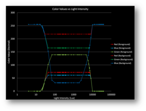
The primary method for obtaining test data for the light compensation was through the use of a flood light. Using this source, the equations for creating the solution was obtained. One of the goals in development was to always have colored buttons and text return to their original colors. This is shown in the following image. During normal light intensity, the RGB values return to their initial value.
Similar to how the test data was obtained, the algorithm testing of the light solution was created using a flood light. The system displayed three randomized strings of characters, on top of buttons, with different contrast ratios between each string and the buttons they were located on. The user was asked to type in the characters they could see when the flood light was turned on. This was repeated when the light compensation was on. The data showed an improvement of 48% (65.7% without compensation to 95.8% with compensation).
The final data output to a .csv file consisted of the average, min, and max light intensity as well as the quantity of missed characters. The system also output the generated and user-entered characters for further analysis. An additional piece of data which should have been measured is the time required to enter the characters. After observation of the experiments, the time required to enter the characters was vastly different depending on the compensation's status.
Conclusion
Our enhanced touchscreen product compensates for both the presence of vibration and changing source light intensities. Varying source light intensity is compensated for by varying the RGB color values of the GUI components to improve visibility. Vibration is compensated for by transforming the GUI to counteract the vibration experienced by the touchscreen system.
To improve upon the ground work laid by this project, a couple routes can be taken. The first would be to add the changing of the screen's light intensity into the algorithm. This could help improve the system's overall usability. Another addition to the project would be to attempt to compensate for vibration in some other fashion. Finally, the project could be continued by compensating for the user's motion as well as the screen's motion.
Team Information
| TEAM MEMBER | BIOGRAPHY
|
|---|---|
| David Barry, E.E.
barr5257@vandals.uidaho.edu |
David Barry is a senior in electrical engineering at the University of Idaho. He is completing his Bachelor's degree before moving onto further his education. He grew up in Oregon and is interested in Mixed Signal Design. He enjoys reading, listening to music, and talking with his friends. |
| Irene D. Agbecha, CompE.
agbe0821@vandals.uidaho.edu |
Irene Agbecha is a computer engineering senior at the University of Idaho (U of I) completing her Bachelor's. She is an international student from Nigeria who came to the U of I as a software engineering transfer student. Her main area of interest is embedded systems design. Her hobbies include writing, playing the guitar, singing, and dancing. |
| Jonathan (Tyler) Simmons, E.E.
simm4031@vandals.uidaho.edu |
Jonathan (Tyler) Simmons is an electrical engineering student at the University of Idaho. Tyler is currently finishing his Bachelor of Science degree in electrical engineering, with an emphasis on control systems, signal processing, and electronics. He was born in Moscow, Idaho but only stayed there for a short time and spent most of his childhood and adolescence in Boise, Idaho. He enjoys researching, reading, video games, and playing guitar. |
